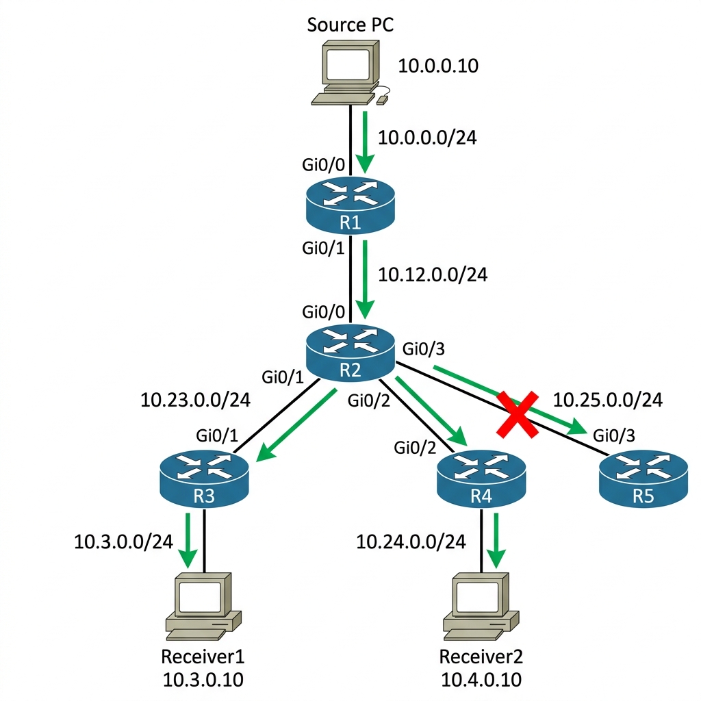
Let me tell you something that took me an embarrassing amount of time to truly appreciate early in my career. I understood multicast conceptually “send once, deliver to many” but I never actually saw unicast fail until I sat in a financial trading floor NOC watching a market data feed choke a 10 Gig uplink because someone decided to unicast the same Bloomberg feed to 400 desktops. That is the day I understood how important Multicast is.
In this first lab, we are going to build a simple network in EVE-NG, prove that unicast is not suitable for some cases, enable multicast, & see the difference. No slides, no theory-first. We configure, we observe, we learn.
What You Will Need
| Component | Quantity | EVE-NG Image |
|---|---|---|
| Cisco IOSv Router | 4 | i86bi_Linux-L3-AdvEnterpriseK9-M2_157_3.bin |
| Cisco IOSv Router (Source) | 1 | i86bi_Linux-L3-AdvEnterpriseK9-M2_157_3.bin |
| Cisco IOSv Router (Receiver) | 3 | i86bi_Linux-L3-AdvEnterpriseK9-M2_157_3.bin |
Total RAM required: approximately 8 GB on your EVE-NG server
Note: You may use a different Cisco Image that supports multicast.
Building the Topology
Here is what we are building. The idea is dead simple one multicast source, one core router, one distribution router, & three receivers hanging off the distribution side. We are using Cisco routers for everything, including the source & receivers, because it makes labbing simple & you do not have to mess around with Linux IP stack quirks.
IP Addressing Table
| Device | Interface | IP Address | Subnet Mask | Description |
|---|---|---|---|---|
| R1 | Gi0/0 | 10.0.0.1 | 255.255.255.0 | To Source |
| R1 | Gi0/1 | 10.12.0.1 | 255.255.255.0 | To R2 |
| R2 | Gi0/0 | 10.12.0.2 | 255.255.255.0 | To R1 |
| R2 | Gi0/1 | 10.23.0.2 | 255.255.255.0 | To R3 |
| R2 | Gi0/2 | 10.24.0.2 | 255.255.255.0 | To R4 |
| R2 | Gi0/3 | 10.25.0.2 | 255.255.255.0 | To R5 |
| R3 | Gi0/1 | 10.23.0.3 | 255.255.255.0 | To R2 |
| R3 | Gi0/0 | 10.3.0.1 | 255.255.255.0 | To Receiver1 |
| R4 | Gi0/2 | 10.24.0.4 | 255.255.255.0 | To R2 |
| R4 | Gi0/0 | 10.4.0.1 | 255.255.255.0 | To Receiver2 |
| R5 | Gi0/3 | 10.25.0.5 | 255.255.255.0 | To R2 (no receiver) |
| Source | Gi0/0 | 10.0.0.10 | 255.255.255.0 | Multicast Source |
| Receiver1 | Gi0/0 | 10.3.0.10 | 255.255.255.0 | Multicast Receiver |
| Receiver2 | Gi0/0 | 10.4.0.10 | 255.255.255.0 | Multicast Receiver |
Step 1 — Basic IP Connectivity (OSPF)
Before we touch anything multicast, we need basic routing. I am going to configure OSPF Area 0 on all routers so that every subnet is reachable.
R1 Configuration:
hostname R1
!
!! Gi0/0 faces the Source host — this is where multicast traffic enters the network
!! Every multicast stream originates from this subnet
interface GigabitEthernet0/0
 ip address 10.0.0.1 255.255.255.0
 no shutdown
!
!! Gi0/1 is the uplink toward R2 (the distribution layer)
!! All multicast traffic from the Source exits R1 through this interface
interface GigabitEthernet0/1
 ip address 10.12.0.1 255.255.255.0
 no shutdown
!
!! OSPF provides the unicast routing table that multicast relies on
!! PIM uses the unicast routing table for RPF (Reverse Path Forwarding) checks
!! Without OSPF, multicast has no idea how to reach sources or the RP
router ospf 1
 network 10.0.0.0 0.0.0.255 area 0
 network 10.12.0.0 0.0.0.255 area 0
R2 Configuration:
hostname R2
!
!! Gi0/0 is the uplink to R1 (source side)
interface GigabitEthernet0/0
 ip address 10.12.0.2 255.255.255.0
 no shutdown
!
!! Gi0/1, Gi0/2, Gi0/3 fan out to R3, R4, R5 respectively
!! R2 is the replication point — when multicast traffic arrives on Gi0/0,
!! R2 decides which downstream interfaces actually need a copy based on
!! whether those branches have active receivers (via PIM Joins)
interface GigabitEthernet0/1
 ip address 10.23.0.2 255.255.255.0
 no shutdown
!
interface GigabitEthernet0/2
 ip address 10.24.0.2 255.255.255.0
 no shutdown
!
interface GigabitEthernet0/3
 ip address 10.25.0.2 255.255.255.0
 no shutdown
!
!! All four subnets go into OSPF Area 0
!! Every subnet must be reachable for multicast to work
router ospf 1
 network 10.12.0.0 0.0.0.255 area 0
 network 10.23.0.0 0.0.0.255 area 0
 network 10.24.0.0 0.0.0.255 area 0
 network 10.25.0.0 0.0.0.255 area 0
R3 Configuration:
%% R3 — Receiver1 side %%
hostname R3
!
interface GigabitEthernet0/1
 ip address 10.23.0.3 255.255.255.0
 no shutdown
!
interface GigabitEthernet0/0
 ip address 10.3.0.1 255.255.255.0
 no shutdown
!
router ospf 1
 network 10.23.0.0 0.0.0.255 area 0
 network 10.3.0.0 0.0.0.255 area 0
R4 Configuration:
%% R4 — Receiver2 side %%
hostname R4
!
interface GigabitEthernet0/2
 ip address 10.24.0.4 255.255.255.0
 no shutdown
!
interface GigabitEthernet0/0
 ip address 10.4.0.1 255.255.255.0
 no shutdown
!
router ospf 1
 network 10.24.0.0 0.0.0.255 area 0
 network 10.4.0.0 0.0.0.255 area 0
R5 Configuration:
%% R5 — Stub router with no receiver (we will use this to prove pruning) %%
hostname R5
!
interface GigabitEthernet0/3
 ip address 10.25.0.5 255.255.255.0
 no shutdown
!
router ospf 1
 network 10.25.0.0 0.0.0.255 area 0
Now let us verify OSPF adjacencies are up.
%% Verify on R2 since it connects to everyone %%
R2# show ip ospf neighbor
Output:
Neighbor ID     Pri   State           Dead Time   Address         Interface
10.0.0.1          1   FULL/DR         00:00:33    10.12.0.1       GigabitEthernet0/0
10.23.0.3         1   FULL/DR         00:00:31    10.23.0.3       GigabitEthernet0/1
10.24.0.4         1   FULL/DR         00:00:35    10.24.0.4       GigabitEthernet0/2
10.25.0.5         1   FULL/DR         00:00:30    10.25.0.5       GigabitEthernet0/3
Verify end-to-end reachability from R1 to the receiver subnets.
R1# ping 10.3.0.10
Output:
Type escape sequence to abort.
Sending 5, 100-byte ICMP Echos to 10.3.0.10, timeout is 2 seconds:
!!!!!
Success rate is 100 percent (5/5), round-trip min/avg/max = 1/2/4 ms
Good. Unicast routing is working. Now let us see what happens when we try to send data to multiple receivers.
Step 2 — The Unicast Problem
Before we configure multicast, let us talk about why it exists.
Imagine our Source at 10.0.0.10 needs to send a live video feed to Receiver1 (10.3.0.10) & Receiver2 (10.4.0.10). With unicast, the source has to send two separate copies of the exact same stream. If that stream is 10 Mbps, the source uplink carries 20 Mbps. If 100 users tune in, the uplink carries 1 Gbps. The router (R1) processes every single packet independently, looking up the destination IP for Receiver1, forwarding it, then doing the exact same thing for Receiver2. This creates massive duplicate traffic on shared links.
Let us conceptually observe this from our Source router. I am going to send 1,000 pings to each receiver simultaneously to simulate duplicate streams.
!! On Source — send unicast traffic to EACH receiver
Source# ping 10.3.0.10 size 1500 repeat 1000
Source# ping 10.4.0.10 size 1500 repeat 1000
Now check R1’s interface counters while traffic is flowing.
R1# show interfaces GigabitEthernet0/1 | include rate
Output:
  5 minute input rate 0 bits/sec, 0 packets/sec
  5 minute output rate 20971520 bits/sec, 1785 packets/sec
Notice that: 20 Mbps on the R1→R2 link, even though the content is identical. If we had 100 receivers, that link would be carrying 1 Gbps of duplicate data. This is exactly what happened on that trading floor I mentioned the upstream links saturate while every downstream port gets a copy that is already on the wire somewhere.
Step 3 — Enabling Multicast (PIM Sparse Mode + IGMP)
Now let us fix this. We are going to enable multicast routing & configure PIM Sparse Mode on every router interface. I am also going to set R1 as the Rendezvous Point (RP). We will talk about What is RP and it’s design in depth later in this series.
R1 — Enable Multicast:
!! This single command is the global on/off switch for multicast
!! Without it, the router completely ignores all PIM & IGMP messages
!! It enables the MFIB (Multicast Forwarding Information Base) in the data plane
R1(config)# ip multicast-routing
!
!! The RP address tells this router where the root of the shared tree lives
!! Every router in the domain MUST have the same RP address configured
!! We are using R1's Gi0/1 IP (10.12.0.1) as the RP for simplicity
R1(config)# ip pim rp-address 10.12.0.1
!
!! PIM sparse-mode must be enabled on EVERY interface that multicast
!! traffic might enter or exit. PIM Hello messages are sent on these
!! interfaces to discover neighbors. If you miss even one transit
!! interface, the multicast tree breaks at that point.
R1(config)# interface GigabitEthernet0/0
R1(config-if)# ip pim sparse-mode
!
R1(config)# interface GigabitEthernet0/1
R1(config-if)# ip pim sparse-mode
R2 — Enable Multicast:
R2(config)# ip multicast-routing
R2(config)# ip pim rp-address 10.12.0.1
!
!! R2 has four interfaces — PIM goes on ALL of them
!! Gi0/0 (uplink to R1) needs PIM so R2 can receive multicast from the source
!! Gi0/1, 0/2, 0/3 (downlinks to R3, R4, R5) need PIM so R2 can
!! forward multicast downstream & receive PIM Joins from those routers
R2(config)# interface GigabitEthernet0/0
R2(config-if)# ip pim sparse-mode
!
R2(config)# interface GigabitEthernet0/1
R2(config-if)# ip pim sparse-mode
!
R2(config)# interface GigabitEthernet0/2
R2(config-if)# ip pim sparse-mode
!
R2(config)# interface GigabitEthernet0/3
R2(config-if)# ip pim sparse-mode
R3 — Enable Multicast:
%% R3 — Enable multicast routing & PIM on all interfaces %%
R3(config)# ip multicast-routing
R3(config)# ip pim rp-address 10.12.0.1
!
R3(config)# interface GigabitEthernet0/0
R3(config-if)# ip pim sparse-mode
!
R3(config)# interface GigabitEthernet0/1
R3(config-if)# ip pim sparse-mode
R4 — Enable Multicast:
%% R4 — Enable multicast routing & PIM on all interfaces %%
R4(config)# ip multicast-routing
R4(config)# ip pim rp-address 10.12.0.1
!
R4(config)# interface GigabitEthernet0/0
R4(config-if)# ip pim sparse-mode
!
R4(config)# interface GigabitEthernet0/1
R4(config-if)# ip pim sparse-mode
R5 — Enable Multicast:
!! R5 has no receiver, but we still enable multicast & PIM on it
!! Why? Because in PIM Sparse Mode, R5 needs to participate in
!! PIM neighbor discovery so that the tree topology is complete.
!! If a receiver appears behind R5 later, PIM is already ready.
!! Also — R2 needs to see R5 as a PIM neighbor to properly
!! decide whether to forward traffic toward it.
R5(config)# ip multicast-routing
R5(config)# ip pim rp-address 10.12.0.1
!
R5(config)# interface GigabitEthernet0/0
R5(config-if)# ip pim sparse-mode
Step 4 — Verify PIM Neighbors
Before anything else, let us make sure PIM adjacencies formed. If PIM neighbors are not up, nothing else will work.
R2# show ip pim neighbor
Output:
PIM Neighbor Table
Mode: B - Bidir Capable, DR - Designated Router, N - Default DR Priority,
      P - Proxy Capable, S - State Refresh Capable, G - GenID Capable
Neighbor          Interface                Uptime/Expires    Ver   DR
Address                                                            Priority/Mode
10.12.0.1         GigabitEthernet0/0       00:02:15/00:01:30 v2    1 / DR S P G
10.23.0.3         GigabitEthernet0/1       00:02:10/00:01:28 v2    1 / S P G
10.24.0.4         GigabitEthernet0/2       00:02:08/00:01:32 v2    1 / S P G
10.25.0.5         GigabitEthernet0/3       00:02:05/00:01:29 v2    1 / S P G
All four neighbors are up. Good.
Step 5 — Receiver Joins a Multicast Group
Now the interesting part. First, a quick dose of Theory: How does a network know who wants multicast traffic? It uses IGMP (Internet Group Management Protocol). When a host wants to receive a stream, it sends an IGMP Membership Report to its default router. That router (in this case R3) then builds multicast routing state to pull that traffic from the network.
I am going to have Receiver1 join multicast group 239.1.1.1 using the igmp join-group command. This forces the router’s interface to act exactly like an end-host requesting multicast traffic.
!! On Receiver1 — join multicast group 239.1.1.1
Receiver1(config)# interface GigabitEthernet0/0
Receiver1(config-if)# ip igmp join-group 239.1.1.1
The moment the receiver joins, the router sends an IGMP Membership Report to 239.1.1.1. Let us watch this from R3’s perspective.
R3# show ip igmp groups
Output:
IGMP Connected Group Membership
Group Address    Interface                Uptime    Expires   Last Reporter
239.1.1.1        GigabitEthernet0/1       00:00:12  00:02:48  10.3.0.10
There it is. R3 now knows that someone on Gi0/1 wants traffic for 239.1.1.1. Let us see what happened in the multicast routing table.
R3# show ip mroute
Output:
IP Multicast Routing Table
Flags: D - Dense, S - Sparse, B - Bidir Group, s - SSM Group, C - Connected,
       L - Local, P - Pruned, R - RP-bit set, F - Register flag,
       T - SPT-bit set, J - Join SPT, M - MSDP created entry,
       E - Extranet, X - Proxy Join Timer Running, A - Candidate for MSDP
       U - URD, I - Received Source Specific Host Report,
       Z - Multicast Tunnel, z - MDT-data group sender,
       Y - Joined MDT-data group, y - Sending to MDT-data group,
       V - RD & Vector, v - Vector
(*, 239.1.1.1), 00:00:12/00:02:48, RP 10.12.0.1, flags: SJC
  Incoming interface: GigabitEthernet0/0, RPF nbr 10.23.0.2
  Outgoing interface list:
    GigabitEthernet0/1, Forward/Sparse, 00:00:12/00:02:48
This is the Shared Tree entry — the (*, 239.1.1.1) or “star-G” entry. The asterisk means “any source.” R3 is saying: “I do not care who sends traffic to 239.1.1.1, I want it, & I will forward it out Gi0/1 to my receiver.”
Notice the incoming interface is Gi0/0 pointing toward R2, which is the path toward the RP (10.12.0.1). This is PIM Sparse Mode doing its job — the receiver’s join propagated up the shared tree toward the RP.
Step 6 — Source Starts Sending Multicast Traffic
Now let us fire up the source using a continuous, large ping to the multicast group.
!! On Source — send multicast traffic to 239.1.1.1
Source# ping 239.1.1.1 repeat 100000 size 1500
Now check the R1→R2 link bandwidth.
R1# show interfaces GigabitEthernet0/1 | include rate
Output:
  5 minute input rate 0 bits/sec, 0 packets/sec
  5 minute output rate 5242880 bits/sec, 446 packets/sec
5 Mbps, not 10 Mbps. Even though we have two potential receivers, the source only sends one copy. R2 replicates it downstream only to the interfaces that have receivers. Let us verify this on R2.
R2# show ip mroute 239.1.1.1
Output:
(*, 239.1.1.1), 00:01:30/00:02:30, RP 10.12.0.1, flags: S
  Incoming interface: GigabitEthernet0/0, RPF nbr 10.12.0.1
  Outgoing interface list:
    GigabitEthernet0/1, Forward/Sparse, 00:01:30/00:02:30

(10.0.0.10, 239.1.1.1), 00:00:45/00:02:15, flags: ST
  Incoming interface: GigabitEthernet0/0, RPF nbr 10.12.0.1
  Outgoing interface list:
    GigabitEthernet0/1, Forward/Sparse, 00:00:45/00:02:15
Two things to notice here:
- R2 is only forwarding out Gi0/1 (toward R3/Receiver1). Gi0/2 & Gi0/3 are not in the outgoing interface list because R4 & R5 have no receivers.
- There are two entries now — the
(*, 239.1.1.1)shared tree entry & the(10.0.0.10, 239.1.1.1)source-specific entry. The “T” flag means the SPT-bit is set — this router has switched to the Shortest Path Tree. We will explore SPT switchover in depth in Article 05.
Step 7 — Adding a Second Receiver
Let us have Receiver2 also join 239.1.1.1.
%% On Receiver2 — join the same multicast group %%
Receiver2(config)# interface GigabitEthernet0/0
Receiver2(config-if)# ip igmp join-group 239.1.1.1
Now check R2’s mroute table again.
R2# show ip mroute 239.1.1.1
Output:
(10.0.0.10, 239.1.1.1), 00:02:10/00:01:50, flags: ST
  Incoming interface: GigabitEthernet0/0, RPF nbr 10.12.0.1
  Outgoing interface list:
    GigabitEthernet0/1, Forward/Sparse, 00:02:10/00:02:50
    GigabitEthernet0/2, Forward/Sparse, 00:00:05/00:02:55
Now Gi0/2 appeared in the outgoing interface list. R2 replicates the single incoming stream to both Gi0/1 & Gi0/2. But check R1’s uplink:
R1# show interfaces GigabitEthernet0/1 | include rate
Output:
5 minute output rate 5242880 bits/sec, 446 packets/sec
Still 5 Mbps.That is the entire point of multicast. The source sends once, & the network replicates only where necessary. If we add 100 more receivers behind R2, the R1→R2 link would still carry just 5 Mbps.
Step 8 — Understanding the Multicast Address Space
Now that we have seen multicast working, let us understand the addressing. Multicast uses Class D IP addresses — the 224.0.0.0/4 range (224.0.0.0 through 239.255.255.255).
| Range | Purpose | Scope |
|---|---|---|
| 224.0.0.0/24 | Link-Local (OSPF, EIGRP, HSRP) | Never forwarded by routers |
| 224.0.1.0/24 | Internetwork Control | Forwarded, used by protocols like NTP |
| 232.0.0.0/8 | Source Specific Multicast (SSM) | Requires IGMPv3 |
| 239.0.0.0/8 | Administratively Scoped | Private multicast (like RFC1918 for unicast) |
In production, you almost always use the 239.x.x.x range for your own multicast applications. The 224.0.0.x range is sacred those addresses are used by routing protocols themselves.
Step 9 — Multicast MAC Address Mapping
Here is something that trips people up in interviews & in real troubleshooting. When a multicast IP packet hits a Layer 2 segment, it needs a destination MAC address. Multicast uses the IEEE-assigned OUI 01:00:5E & maps the lower 23 bits of the IP address into the MAC.
The mapping formula:
Multicast IP:  239.1.1.1
Binary (last 23 bits): 000 0001.0000 0001.0000 0001
Multicast MAC: 01:00:5E:01:01:01
The catch, There are 28 bits in the multicast IP group ID but only 23 bits in the MAC address. That means 32 different multicast IP addresses map to the same MAC address. For example, 239.1.1.1 & 239.129.1.1 produce the same MAC. In real life, this causes a host receiving multicast traffic it did not ask for the NIC accepts it, & the IP stack drops it. It is a minor CPU overhead
R3# show ip igmp groups 239.1.1.1 detail
Output:
Interface:      GigabitEthernet0/1
Group:          239.1.1.1
Flags:
Uptime:         00:05:30
Group mode:     EXCLUDE (IGMPv2 compatibility)
Last reporter:  10.3.0.10
Source list is empty
Break It — Remove PIM from a Transit Interface
Now the fun part. I am going to deliberately break multicast & show you what the failure looks like. This is the most common multicast failure in production — someone forgets to enable PIM on a transit interface.
!! On R2 — remove PIM from the interface toward R3
R2(config)# interface GigabitEthernet0/1
R2(config-if)# no ip pim sparse-mode
Immediately, check R2’s PIM neighbors.
R2# show ip pim neighbor
Output:
PIM Neighbor Table
Neighbor          Interface                Uptime/Expires    Ver   DR
Address                                                            Priority/Mode
10.12.0.1         GigabitEthernet0/0       00:10:15/00:01:30 v2    1 / DR S P G
10.24.0.4         GigabitEthernet0/2       00:10:08/00:01:32 v2    1 / S P G
10.25.0.5         GigabitEthernet0/3       00:10:05/00:01:29 v2    1 / S P G
R3 is gone from the PIM neighbor list. Now check R2’s mroute.
R2# show ip mroute 239.1.1.1
Output:
(10.0.0.10, 239.1.1.1), 00:05:10/00:02:50, flags: ST
  Incoming interface: GigabitEthernet0/0, RPF nbr 10.12.0.1
  Outgoing interface list:
    GigabitEthernet0/2, Forward/Sparse, 00:02:05/00:02:55
Gi0/1 is gone from the outgoing interface list. R2 can no longer forward multicast toward R3 because PIM is not running on that interface. Receiver1 is now dark it is not getting any multicast traffic, even though IGMP is still perfectly fine between R3 & Receiver1.
This is the insidious part of this failure. If you only check IGMP on the last-hop router (R3), everything looks healthy. R3 still has the IGMP group membership. The problem is upstream the PIM join from R3 never reaches R2 because PIM is not running on R2’s Gi0/1.
Let us verify from R3’s perspective.
R3# show ip igmp groups
Output:
Group Address    Interface                Uptime    Expires   Last Reporter
239.1.1.1        GigabitEthernet0/1       00:06:00  00:02:00  10.3.0.10
See? IGMP is fine. The receiver thinks it has joined. But check R3’s mroute.
R3# show ip mroute 239.1.1.1
Output:
(*, 239.1.1.1), 00:06:00/stopped, RP 10.12.0.1, flags: SJC
  Incoming interface: GigabitEthernet0/0, RPF nbr 10.23.0.2
  Outgoing interface list:
    GigabitEthernet0/1, Forward/Sparse, 00:06:00/00:02:00

(10.0.0.10, 239.1.1.1), 00:05:00/00:02:00, flags: SJT
  Incoming interface: GigabitEthernet0/0, RPF nbr 10.23.0.2
  Outgoing interface list:
    GigabitEthernet0/1, Forward/Sparse, 00:05:00/00:02:00
R3 has the mroute entry & it is trying to pull traffic through Gi0/0, but R2 is not sending anything because PIM is down on that link between them.
The fix is simple:
%% On R2 — re-enable PIM on the interface %%
R2(config)# interface GigabitEthernet0/1
R2(config-if)# ip pim sparse-mode
Within seconds, R2 & R3 re-form their PIM neighbor adjacency, the PIM Join from R3 reaches R2 again, & multicast traffic resumes to Receiver1.
One mistake I have seen multiple times in production: someone enables PIM on all routed interfaces using ip pim sparse-mode but forgets to add it on a newly created subinterface or VLAN SVI. Traffic for that segment just silently stops.
Key Takeaways
- Unicast does not scale for one-to-many delivery. The source link carries N copies of the same stream, where N is the number of receivers.
- Multicast sends once — the network replicates at fork points only where receivers exist.
- Three things must be configured for basic multicast:
ip multicast-routing,ip pim sparse-modeon every transit & receiver interface, & a Rendezvous Point. - PIM must be enabled on EVERY interface in the multicast path — not just the source & receiver interfaces. Missing PIM on a transit link is the #1 cause of multicast outages.
- Multicast addresses use the 224.0.0.0/4 range. Use 239.x.x.x for your applications.
- The MAC mapping uses 01:00:5E + lower 23 bits of the IP — leading to 32:1 address overlap.