Here is something that catches a lot of engineers off-guard. They configure PIM, set up the RP, multicast “works,” & they move on. Then six months later, a receiver stops getting traffic & nobody can figure out why. Nine times out of ten, the problem is not PIM — it is IGMP. The protocol that sits between the receiver & the first-hop router is where most multicast failures actually live, & yet most engineers treat it like a checkbox they never need to look at again.
In this lab, we are going to watch every IGMP message type happen in real-time. We will see joins, leaves, queries, & querier elections play out on our console. By the end of this, you will know exactly what debug ip igmp output means & where to look when receivers go dark.
What You Will Need
| Component | Quantity | EVE-NG Image |
|---|---|---|
| Cisco IOSv Router (Network) | 2 | i86bi_Linux-L3-AdvEnterpriseK9-M2_157_3_May_2018.bin |
| Cisco IOSv Router (Source/Receiver) | 4 | i86bi_Linux-L3-AdvEnterpriseK9-M2_157_3_May_2018.bin |
| Cisco IOSvL2 Switch | 1 | i86bi_Linux-L2-AdvEnterpriseK9-M_152_May_2018.bin |
Note: You may use a different version of IOS to simulate the lab with identical results.
Lab Topology
We are building a standard campus-style multicast segment. R1 is our core/RP, R2 is our distribution router (the “First-Hop Router” for IGMP), & SW1 is the access switch where multiple receivers are hanging off the same VLAN. This “multi-access” segment is critical for seeing how IGMP behaves when multiple hosts are in the same group.
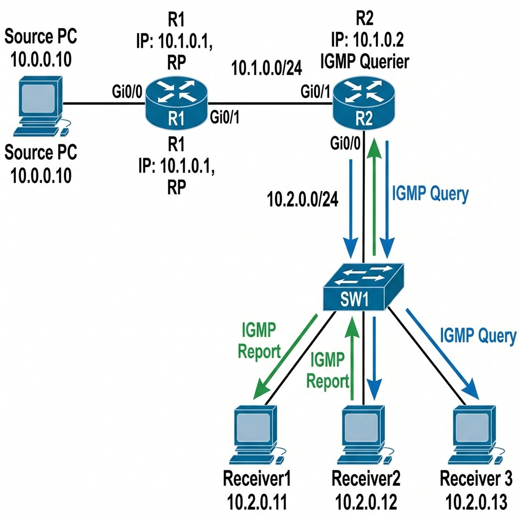
IP Addressing Table
| Device | Interface | IP Address | Subnet Mask | Description |
|---|---|---|---|---|
| R1 | Gi0/0 | 10.0.0.1 | 255.255.255.0 | To Source |
| R1 | Gi0/1 | 10.1.0.1 | 255.255.255.0 | To R2 |
| R1 | Loopback0 | 1.1.1.1 | 255.255.255.255 | RP Address |
| R2 | Gi0/0 | 10.1.0.2 | 255.255.255.0 | To R1 |
| R2 | Gi0/1 | 10.2.0.1 | 255.255.255.0 | To SW1 (Receiver LAN) |
| SW1 | VLAN 1 | 10.2.0.254 | 255.255.255.0 | Management |
| Source | Gi0/0 | 10.0.0.10 | 255.255.255.0 | Multicast Source |
| Receiver1 | Gi0/0 | 10.2.0.11 | 255.255.255.0 | IGMP Host |
| Receiver2 | Gi0/0 | 10.2.0.12 | 255.255.255.0 | IGMP Host |
| Receiver3 | Gi0/0 | 10.2.0.13 | 255.255.255.0 | IGMP Host |
Step 1 — Base Configuration
R1 Configuration:
hostname R1
!
!! Loopback0 serves as the RP address — a Loopback is ideal because
!! it never goes down (unlike physical interfaces), so the RP remains
!! reachable even if a physical link flaps. PIM sparse-mode on the
!! Loopback is necessary because the RP must be a PIM-enabled interface.
interface Loopback0
 ip address 1.1.1.1 255.255.255.255
 ip pim sparse-mode
!
!! Gi0/0 faces the Source — multicast traffic enters the network here.
!! PIM on this interface lets R1 act as the first-hop router (DR) for
!! the source, which is responsible for sending PIM Register messages to the RP.
interface GigabitEthernet0/0
 ip address 10.0.0.1 255.255.255.0
 ip pim sparse-mode
 no shutdown
!
!! Gi0/1 connects to R2 — the transit link carrying both PIM control
!! messages & multicast data traffic toward the receiver network
interface GigabitEthernet0/1
 ip address 10.1.0.1 255.255.255.0
 ip pim sparse-mode
 no shutdown
!
!! OSPF advertises the Loopback0 (1.1.1.1) so all routers can reach the RP
!! Without this, no router can find the RP & multicast is completely dead
router ospf 1
 network 1.1.1.1 0.0.0.0 area 0
 network 10.0.0.0 0.0.0.255 area 0
 network 10.1.0.0 0.0.0.255 area 0
!
!! Global multicast switch — required before any PIM/IGMP processing
ip multicast-routing
!! All routers point to the same RP — consistency is critical
ip pim rp-address 1.1.1.1
R2 Configuration:
hostname R2
!
!! Gi0/0 is the uplink toward R1 & the RP
interface GigabitEthernet0/0
 ip address 10.1.0.2 255.255.255.0
 ip pim sparse-mode
 no shutdown
!
!! Gi0/1 faces the receiver LAN — THIS is the IGMP interface
!! This is where all the IGMP action happens: Queries go out,
!! Membership Reports come in, Leave messages arrive.
!! We explicitly set IGMPv2 here so we can compare with v3 later.
!! The router automatically becomes the IGMP Querier on this
!! segment because it is the only PIM router (for now).
interface GigabitEthernet0/1
 ip address 10.2.0.1 255.255.255.0
 ip pim sparse-mode
 ip igmp version 2
 no shutdown
!
router ospf 1
 network 10.1.0.0 0.0.0.255 area 0
 network 10.2.0.0 0.0.0.255 area 0
!
ip multicast-routing
ip pim rp-address 1.1.1.1
SW1 Configuration:
hostname SW1
!
!! All ports are access ports in VLAN 1 — a flat L2 domain
!! The switch sits between R2 & the receivers, forwarding
!! IGMP messages transparently (for now — snooping is in Article 03)
interface range GigabitEthernet0/0 - 3
 switchport mode access
 switchport access vlan 1
 no shutdown
!
!! VLAN1 SVI is for management only — the switch needs an IP
!! to be reachable & potentially serve as IGMP snooping querier later
interface Vlan1
 ip address 10.2.0.254 255.255.255.0
 no shutdown
!
!! Default gateway points to R2 so the switch can reach remote subnets
ip default-gateway 10.2.0.1
Source & Receiver Configuration (Cisco Routers):
To keep things simple, we’ll just configure the IP & a default gateway on these “end hosts.” We disable routing so they act like standard hosts.
!! Example for Receiver 1 (repeat for Source, Recv2, Recv3 with their IPs)
hostname Receiver1
!
no ip routing
!
interface GigabitEthernet0/0
 ip address 10.2.0.11 255.255.255.0
 no shutdown
!
ip default-gateway 10.2.0.1
Verify OSPF & PIM neighbors are healthy.
R2# show ip pim neighbor
Output:
PIM Neighbor Table
Neighbor          Interface                Uptime/Expires    Ver   DR
Address                                                            Priority/Mode
10.1.0.1          GigabitEthernet0/0       00:03:21/00:01:15 v2    1 / S P G
Good. R2 sees R1 as a PIM neighbor. R2’s show ip
Step 2 — Watching an IGMP Join in Real-Time
The Theory: IGMP (Internet Group Management Protocol) is how a receiver tells the network “I want this multicast stream.” Without it, the router has no idea where the receivers are. In PIM Sparse Mode, this IGMP Join is the trigger that makes the router send a PIM Join message upstream toward the RP.
I am going to enable debug ip igmp on R2 & then have Receiver1 join a multicast group. Watch the console carefully.
R2# debug ip igmp
IGMP debugging is on
Now on Receiver1, join group 239.1.1.1. Instead of a Linux command, we use the ip igmp join-group command on the Cisco router interface.
!! On Receiver1 — join multicast group 239.1.1.1
Receiver1(config)# interface GigabitEthernet0/0
Receiver1(config-if)# ip igmp join-group 239.1.1.1
Watch R2’s console:
*Apr 19 00:15:32.001: IGMP(0): Received v2 Report on GigabitEthernet0/1 from 10.2.0.11 for 239.1.1.1
*Apr 19 00:15:32.002: IGMP(0): Received Group record for group 239.1.1.1, mode 2 from 10.2.0.11 for 0 sources
*Apr 19 00:15:32.003: IGMP(0): Updating EXCLUDE group timer for 239.1.1.1
*Apr 19 00:15:32.004: IGMP(0): MRT Add/Update GigabitEthernet0/1 for (*,239.1.1.1) by 0
Let us break down what just happened:
- Receiver1 (10.2.0.11) sent an IGMPv2 Membership Report to 239.1.1.1
- R2 received it on Gi0/1 & created a group membership entry
- R2 updated its internal timer for this group (default 260 seconds)
- R2 triggered a PIM (
*, 239.1.1.1) Join toward the RP
Verify the group membership:
R2# show ip igmp groups
Output:
IGMP Connected Group Membership
Group Address    Interface                Uptime    Expires   Last Reporter
239.1.1.1        GigabitEthernet0/1       00:00:15  00:04:05  10.2.0.11
The Expires timer is critical. This is the Group Membership Timer — if R2 does not receive another IGMP Report for this group before it expires, R2 assumes all receivers have left & removes the group.
Step 3 — The IGMP Query Mechanism
How does R2 know if receivers are still there? It sends periodic IGMP General Queries to 224.0.0.1 (All Hosts). Every multicast-capable host that hears this query must re-send its Membership Report.
Let us see the query settings.
R2# show ip igmp interface GigabitEthernet0/1
Output:
GigabitEthernet0/1 is up, line protocol is up
  Internet address is 10.2.0.1/24
  IGMP is enabled on interface
  Current IGMP host version is 2
  Current IGMP router version is 2
  IGMP query interval is 60 seconds
  IGMP configured query interval is 60 seconds
  IGMP querier timeout is 120 seconds
  IGMP configured querier timeout is 120 seconds
  IGMP max query response time is 10 seconds
  Last member query count is 2
  Last member query response interval is 1000 ms
  Inbound IGMP access group is not set
  IGMP activity: 1 joins, 0 leaves
  Multicast routing is enabled on interface
  Multicast TTL threshold is 0
  Multicast designated router (DR) is 10.2.0.1 (this system)
  IGMP querying router is 10.2.0.1 (this system)
  Multicast groups joined by this system:
    224.0.1.40
Key timers to understand:
| Timer | Default (IGMPv2) | What It Does |
|---|---|---|
| Query Interval | 60 seconds | How often the querier sends General Queries |
| Max Query Response Time | 10 seconds | How long hosts have to respond |
| Group Membership Timeout | 260 seconds | = (Robustness × Query Interval) + Max Response Time |
| Last Member Query Interval | 1 second | How fast the router queries after a Leave |
| Last Member Query Count | 2 | How many Group-Specific Queries after a Leave |
==The Group Membership Timeout (260s) is not directly configurable — it is derived from the formula above.== If you want faster failure detection, you reduce the Query Interval & Max Response Time. But be careful — in large networks with thousands of groups, aggressive timers create a storm of IGMP traffic.
Step 4 — Watching a Leave in Real-Time
The Theory: When a receiver is done, it sends an IGMP Leave Group message (to 224.0.0.2 – All Routers). In IGMPv2, this is a “best effort” message. The router doesn’t immediately stop the stream; it first sends a Group-Specific Query to see if anyone else on the same segment still wants the traffic. This is essential for shared media.
Now let us have Receiver1 leave the group & watch exactly what happens.
%% On Receiver1 — leave the group %%
Receiver1(config)# interface GigabitEthernet0/0
Receiver1(config-if)# no ip igmp join-group 239.1.1.1
Watch R2’s debug output:
*Apr 19 00:18:45.100: IGMP(0): Received Leave from 10.2.0.11 (GigabitEthernet0/1) for 239.1.1.1
*Apr 19 00:18:45.101: IGMP(0): Send v2 Query on GigabitEthernet0/1 for group 239.1.1.1
*Apr 19 00:18:46.101: IGMP(0): Send v2 Query on GigabitEthernet0/1 for group 239.1.1.1
*Apr 19 00:18:47.200: IGMP(0): Deleting 239.1.1.1 on GigabitEthernet0/1
Here is what happened step-by-step:
- Receiver1 sent an IGMP Leave Group message to 224.0.0.2 (All Routers)
- R2 received the Leave & immediately sent a Group-Specific Query to 239.1.1.1 on that interface — basically asking “is anyone else still listening?”
- R2 sent a second Group-Specific Query (Last Member Query Count = 2)
- Nobody responded, so R2 deleted the group membership after the Last Member Query Interval expired
This is where IGMPv2 is actually pretty clever. The router does not immediately remove the group just because one host sent a Leave. It checks if anyone else is still interested. This matters because on a shared LAN segment, multiple hosts might be in the same group.
Let us add Receiver1 & Receiver2 to the same group, then remove only Receiver1. This will demonstrate how the router handles multiple hosts.
!! On Receiver1
Receiver1(config)# interface GigabitEthernet0/0
Receiver1(config-if)# ip igmp join-group 239.1.1.1

!! On Receiver2
Receiver2(config)# interface GigabitEthernet0/0
Receiver2(config-if)# ip igmp join-group 239.1.1.1
R2# show ip igmp groups
Output:
Group Address    Interface                Uptime    Expires   Last Reporter
239.1.1.1        GigabitEthernet0/1       00:00:20  00:04:00  10.2.0.12
Notice Last Reporter is now 10.2.0.12 (Receiver2). This is because of IGMP Report Suppression in IGMPv2 — when Receiver1 heard Receiver2’s report, it suppressed its own to reduce traffic.
Now remove Receiver1:
%% On Receiver1 — leave the group %%
Receiver1(config)# interface GigabitEthernet0/0
Receiver1(config-if)# no ip igmp join-group 239.1.1.1
Watch R2’s debug:
*Apr 19 00:20:10.100: IGMP(0): Received Leave from 10.2.0.11 (GigabitEthernet0/1) for 239.1.1.1
*Apr 19 00:20:10.101: IGMP(0): Send v2 Query on GigabitEthernet0/1 for group 239.1.1.1
*Apr 19 00:20:11.050: IGMP(0): Received v2 Report on GigabitEthernet0/1 from 10.2.0.12 for 239.1.1.1
Receiver2 responded to the Group-Specific Query, so R2 kept the group membership alive. The group is not deleted because there is still an active receiver.
Step 5 — IGMP Querier Election
On a multi-access network, only one router should send IGMP queries. If multiple routers query, you get duplicate state & wasted bandwidth. The router with the lowest IP address wins the Querier election.
Right now R2 (10.2.0.1) is the only router on the receiver LAN, so it is the querier by default. Let us add a second router to the segment & watch the election happen.
I am going to connect R1’s Gi0/2 directly to SW1 with IP 10.2.0.2. This gives us two PIM routers on the same LAN.
!! On R1 — add a new interface to the receiver LAN
R1(config)# interface GigabitEthernet0/2
R1(config-if)# ip address 10.2.0.2 255.255.255.0
R1(config-if)# ip pim sparse-mode
R1(config-if)# no shutdown
Now check the querier election on both routers.
R2# show ip igmp interface GigabitEthernet0/1 | include querier
Output:
IGMP querying router is 10.2.0.1 (this system)
R2 (10.2.0.1) wins the election because 10.2.0.1 < 10.2.0.2. R2 will continue sending General Queries, & R1 will become a Non-Querier (it listens but does not query).
R1# show ip igmp interface GigabitEthernet0/2 | include querier
Output:
IGMP querying router is 10.2.0.1
R1 acknowledges that R2 is the querier. If R2 goes down, R1 will take over querier duties after the Querier Timeout (120 seconds by default).
Step 6 — IGMPv2 vs IGMPv3 Comparison
Let us now switch to IGMPv3 & see what changes. IGMPv3 adds Source Filtering — a receiver can say “I want traffic for group 239.1.1.1, but ONLY from source 10.0.0.10.” This is the foundation of SSM (Source Specific Multicast).
!! On R2 — change to IGMPv3
R2(config)# interface GigabitEthernet0/1
R2(config-if)# ip igmp version 3
Now have a receiver join with source filtering using the ip igmp join-group 239.1.1.1 source 10.0.0.10 command.
!! On Receiver1 — join with source filter (IGMPv3)
Receiver1(config)# interface GigabitEthernet0/0
Receiver1(config-if)# ip igmp join-group 239.1.1.1 source 10.0.0.10
R2# show ip igmp groups detail
Output:
Interface:      GigabitEthernet0/1
Group:          239.1.1.1
Flags:
Uptime:         00:00:10
Group mode:     INCLUDE
Last reporter:  10.2.0.11
Group source list: (C - Cisco different from different IGMPv3 host report)
  Source Address   Uptime    Expires   Fwd  Flags
  10.0.0.10        00:00:10  00:04:10  Yes
Key differences from IGMPv2:
- Group mode is INCLUDE — the host explicitly listed which sources it wants
- Source list shows 10.0.0.10 — only traffic from this source will be forwarded
- Report Suppression is disabled in IGMPv3 — every host sends its own report because each host may have different source filters
In IGMPv2, the router has no idea which source the receiver wants it just knows “someone wants 239.1.1.1.” In IGMPv3, the router knows exactly which source-group pair is needed. This is a massive improvement for security & efficiency.
Step 7 — IGMP Timers Tuning for Fast Failover
In production IPTV deployments, the default IGMP timers are way too slow. If a customer changes the channel (leaves one group, joins another), you do not want to wait 260 seconds for the old group to time out. Let us tune the timers for fast leave behavior.
R2(config)# interface GigabitEthernet0/1
!
!! Cut the query interval in half — queries now sent every 30s instead of 60s
!! This means receivers are polled more frequently & stale groups are
!! detected faster (Group Membership Timeout drops from 260s to 65s)
R2(config-if)# ip igmp query-interval 30
!
!! Reduce response window from 10s to 5s — hosts must respond faster
!! This directly reduces the Group Membership Timeout calculation
R2(config-if)# ip igmp query-max-response-time 5
!
!! After a Leave, send the Group-Specific Query with a 500ms response
!! window instead of the default 1000ms — faster channel changes
R2(config-if)# ip igmp last-member-query-interval 500
!
!! Only send ONE Group-Specific Query after a Leave instead of two
!! Combined with the 500ms interval, a Leave is processed in 500ms
!! instead of the default 2000ms (2 queries × 1000ms)
R2(config-if)# ip igmp last-member-query-count 1
Now verify the new settings:
R2# show ip igmp interface GigabitEthernet0/1
Output:
  IGMP query interval is 30 seconds
  IGMP max query response time is 5 seconds
  Last member query count is 1
  Last member query response interval is 500 ms
With these settings:
– General Queries are sent every 30 seconds instead of 60
– Group Membership Timeout = (2 × 30) + 5 = 65 seconds (down from 260)
– After a Leave, only 1 Group-Specific Query is sent with a 500ms response window
For IPTV, some operators go even more aggressive ip igmp immediate-leave group-list skips the Group-Specific Query entirely & removes the group the instant a Leave is received. But this only works on point-to-point links (one host per interface). On shared LAN segments, immediate-leave will kill the stream for everyone else.
!! Immediate leave — ONLY use on point-to-point links
R2(config)# interface GigabitEthernet0/1
R2(config-if)# ip igmp immediate-leave group-list ALL_MULTICAST
!
R2(config)# ip access-list standard ALL_MULTICAST
R2(config-std-nacl)# permit 239.0.0.0 0.255.255.255
Break It — IGMP Version Mismatch
Now let us create a very common production failure. I am going to set R2’s interface to IGMPv3, but configure the receiver to send IGMPv2 reports. In theory, IGMPv3 is backward compatible — but let us see what actually happens when things are misconfigured.
%% On R2 — set to IGMPv3 strictly %%
R2(config)# interface GigabitEthernet0/1
R2(config-if)# ip igmp version 3
Now if Receiver1 sends an IGMPv2-style join (no source filtering), the router operates in IGMPv3 compatibility mode:
!! On Receiver1 — join WITHOUT source filter (IGMPv2 style)
Receiver1(config)# interface GigabitEthernet0/0
Receiver1(config-if)# ip igmp join-group 239.1.1.1
R2# show ip igmp groups detail
Output:
Interface:      GigabitEthernet0/1
Group:          239.1.1.1
Flags:
Uptime:         00:00:08
Group mode:     EXCLUDE (IGMPv2 compatibility)
Last reporter:  10.2.0.11
Source list is empty
The router fell back to EXCLUDE mode (basically IGMPv2 behavior). This works, but it means you lose all IGMPv3 source filtering benefits.
Now here is the real problem scenario. What if someone explicitly forces IGMPv2 on the router interface but the host is sending IGMPv3?
R2(config)# interface GigabitEthernet0/1
R2(config-if)# ip igmp version 2
R2# debug ip igmp
If the host sends an IGMPv3 report to an IGMPv2-only interface:
*Apr 19 00:35:10.100: IGMP(0): Received v3 Report on GigabitEthernet0/1 from 10.2.0.11
*Apr 19 00:35:10.101: IGMP(0): Received v3 Report on GigabitEthernet0/1 - not IGMPv2 compatible, ignored
The router ignores the report entirely. The receiver thinks it has joined successfully (from its perspective, it sent the report), but R2 never created a group membership entry. This is a silent failure no error messages, no logs unless you have debug on. The receiver just never gets traffic.
The fix:
!! Either upgrade the router to IGMPv3
R2(config-if)# ip igmp version 3

!! Or downgrade the host to IGMPv2
!! On Linux:
echo 2 > /proc/sys/net/ipv4/conf/eth0/force_igmp_version
In real networks, always check IGMP version consistency between hosts & routers. This is the single most common “everything looks configured correctly but nothing works” scenario in multicast.
Common IGMP Verification Commands
Here is the verification command cheat sheet I use in production:
!! Check which groups are joined on an interface
show ip igmp groups [interface]

!! Check detailed group info with source lists (IGMPv3)
show ip igmp groups detail

!! Check IGMP interface settings & querier status
show ip igmp interface [interface]

!! Check group membership timers
show ip igmp membership

!! Enable IGMP debugging (use with caution in production)
debug ip igmp

!! Check IGMP snooping state on switches
show ip igmp snooping
show ip igmp snooping groups
Key Takeaways
- IGMP is the receiver-to-router protocol — it tells the first-hop router which multicast groups have active listeners
- IGMPv2 uses Report Suppression — only one host per segment reports for each group. This saves bandwidth but hides how many receivers actually exist.
- IGMPv3 adds source filtering — the foundation of SSM. Each host reports independently.
- The Querier is elected by lowest IP on the segment. Only one router sends General Queries.
- Timer tuning matters — the default 260-second group timeout is way too slow for IPTV & real-time applications.
- Version mismatches fail silently — always verify that routers & hosts agree on IGMP version.
ip igmp immediate-leaveis powerful but dangerous on shared segments — only use on point-to-point links.