If there is one protocol you absolutely must understand inside-out to call yourself a multicast engineer, it is PIM Sparse Mode. This is the protocol running behind every IPTV deployment, every Bloomberg market data feed, every Webex multicast stream, & every large-scale video distribution network on the planet. Dense Mode was the experiment — Sparse Mode is the production reality.
In this lab, we are going to build a 5-router PIM-SM network from scratch. We will watch every phase of the multicast tree lifecycle: receiver joins the shared tree, source registers with the RP, traffic flows through the RP, & then the SPT switchover happens. Step by step, router by router, with show ip mroute at every stage so you can see exactly how the state evolves. This is the article I wish someone had written for me when I was studying for my CCIE.
Core Concepts: RP and Shared Tree
Before we jump into the CLI, let’s establish the two most critical concepts in PIM Sparse Mode that make it fundamentally different from Dense Mode:
The Rendezvous Point (RP):
In Sparse Mode, multicast traffic is not flooded everywhere. Instead, we need a central meeting place where multicast sources and receivers can find each other. This is the Rendezvous Point (RP). Think of it as a central post office for multicast. Sources send their multicast traffic directly to the RP, and receivers explicitly ask the RP to send them that traffic. Every router in the PIM Sparse Mode domain must agree on exactly who the RP is.
The Shared Tree (*,G):
Because all receivers pull traffic from the RP rather than directly from the source, the initial multicast distribution tree is rooted at the RP. This is called the Shared Tree or Rendezvous Point Tree (RPT). It is represented in the multicast routing table as (*, G) — meaning “traffic for Group G, from any source.” The Shared Tree is highly scalable because transit routers only need to maintain one forwarding state per group, regardless of how many different sources are transmitting to that group.
What You Will Need
| Component | Quantity | EVE-NG Image |
|---|---|---|
| Cisco IOSv Router (Network) | 5 | i86bi_Linux-L3-AdvEnterpriseK9-M2_157_3_May_2018.bin |
| Cisco IOSv Router (Source/Receiver) | 2 | i86bi_Linux-L3-AdvEnterpriseK9-M2_157_3_May_2018.bin |
Total RAM required: approximately 4 GB.
Lab Topology
This topology is deliberately designed with the RP (R3) positioned between the source & receiver, but not on the shortest path. This lets us clearly observe the RPT → SPT switchover.
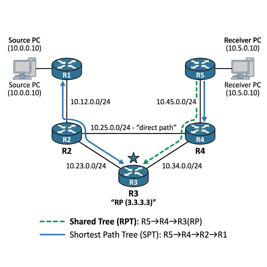
The key design here: the shortest path from R1 (source) to R5 (receiver) is R1→R2→R4→R5 via the direct link. But the shared tree goes through the RP at R3, which is longer: R1→R2→R3 (RP) and R3→R4→R5. We will see both paths in action.
IP Addressing Table
| Device | Interface | IP Address | Subnet Mask | Description |
|---|---|---|---|---|
| R1 | Gi0/0 | 10.0.0.1 | 255.255.255.0 | To Source |
| R1 | Gi0/1 | 10.12.0.1 | 255.255.255.0 | To R2 |
| R2 | Gi0/0 | 10.12.0.2 | 255.255.255.0 | To R1 |
| R2 | Gi0/1 | 10.23.0.2 | 255.255.255.0 | To R3 |
| R2 | Gi0/2 | 10.25.0.2 | 255.255.255.0 | To R4 (direct path) |
| R3 | Gi0/0 | 10.23.0.3 | 255.255.255.0 | To R2 |
| R3 | Gi0/1 | 10.34.0.3 | 255.255.255.0 | To R4 |
| R3 | Loopback0 | 3.3.3.3 | 255.255.255.255 | RP Address |
| R4 | Gi0/0 | 10.34.0.4 | 255.255.255.0 | To R3 |
| R4 | Gi0/1 | 10.45.0.4 | 255.255.255.0 | To R5 |
| R4 | Gi0/2 | 10.25.0.4 | 255.255.255.0 | To R2 (direct path) |
| R5 | Gi0/0 | 10.45.0.5 | 255.255.255.0 | To R4 |
| R5 | Gi0/1 | 10.5.0.1 | 255.255.255.0 | To Receiver |
| Source | Gi0/0 | 10.0.0.10 | 255.255.255.0 | Multicast Source |
| Receiver | Gi0/0 | 10.5.0.10 | 255.255.255.0 | Multicast Receiver |
Step 1 — Full Configurations
R1 Configuration:
hostname R1
!
!! Gi0/0 faces the Source — this is where the first-hop router (DR)
!! responsibility kicks in. When R1 receives multicast on this interface
!! and there is no (*,G) tree from the RP, R1 encapsulates the traffic
!! inside a PIM Register message and unicasts it to the RP.
interface GigabitEthernet0/0
 ip address 10.0.0.1 255.255.255.0
 ip pim sparse-mode
 no shutdown
!
!! Gi0/1 is R1's path toward R2 and ultimately the RP at R3
!! PIM Joins from the RP will arrive through this interface
interface GigabitEthernet0/1
 ip address 10.12.0.1 255.255.255.0
 ip pim sparse-mode
 no shutdown
!
router ospf 1
 network 10.0.0.0 0.0.0.255 area 0
 network 10.12.0.0 0.0.0.255 area 0
!
!! ip multicast-routing enables the MFIB data plane
!! ip pim rp-address MUST match on every router in the domain
!! R1 needs to know where 3.3.3.3 is so it can send PIM Register messages
ip multicast-routing
ip pim rp-address 3.3.3.3
R2 Configuration:
hostname R2
!
interface GigabitEthernet0/0
 ip address 10.12.0.2 255.255.255.0
 ip pim sparse-mode
 no shutdown
!
interface GigabitEthernet0/1
 ip address 10.23.0.2 255.255.255.0
 ip pim sparse-mode
 no shutdown
!
interface GigabitEthernet0/2
 ip address 10.25.0.2 255.255.255.0
 ip pim sparse-mode
 no shutdown
!
router ospf 1
 network 10.12.0.0 0.0.0.255 area 0
 network 10.23.0.0 0.0.0.255 area 0
 network 10.25.0.0 0.0.0.255 area 0
!
ip multicast-routing
ip pim rp-address 3.3.3.3
R3 Configuration (RP):
hostname R3
!
!! Loopback0 is the RP address — 3.3.3.3
!! Using a Loopback as the RP is critical because:
!! 1. It is always up (does not flap with physical interfaces)
!! 2. It is reachable from any direction in the topology
!! 3. PIM sparse-mode on the Loopback is required because the RP
!!    address must be a PIM-enabled interface for Register processing
interface Loopback0
 ip address 3.3.3.3 255.255.255.255
 ip pim sparse-mode
!
!! Gi0/0 connects to R2 (source side)
!! PIM Register messages from R1 arrive through this path
interface GigabitEthernet0/0
 ip address 10.23.0.3 255.255.255.0
 ip pim sparse-mode
 no shutdown
!
!! Gi0/1 connects to R4 (receiver side)
!! PIM Joins from R5 propagate toward the RP through this path
interface GigabitEthernet0/1
 ip address 10.34.0.3 255.255.255.0
 ip pim sparse-mode
 no shutdown
!
!! CRITICAL: the Loopback0 MUST be in OSPF so all routers can find the RP
!! If you forget this line, no router can reach 3.3.3.3 and all multicast breaks
!! (this exact mistake is Scenario 2 in Article 09's troubleshooting lab)
router ospf 1
 network 3.3.3.3 0.0.0.0 area 0
 network 10.23.0.0 0.0.0.255 area 0
 network 10.34.0.0 0.0.0.255 area 0
!
ip multicast-routing
!! The RP also points to itself — this is normal & required
ip pim rp-address 3.3.3.3
R4 Configuration:
hostname R4
!
interface GigabitEthernet0/0
 ip address 10.34.0.4 255.255.255.0
 ip pim sparse-mode
 no shutdown
!
interface GigabitEthernet0/1
 ip address 10.45.0.4 255.255.255.0
 ip pim sparse-mode
 no shutdown
!
interface GigabitEthernet0/2
 ip address 10.25.0.4 255.255.255.0
 ip pim sparse-mode
 no shutdown
!
router ospf 1
 network 10.34.0.0 0.0.0.255 area 0
 network 10.45.0.0 0.0.0.255 area 0
 network 10.25.0.0 0.0.0.255 area 0
!
ip multicast-routing
ip pim rp-address 3.3.3.3
R5 Configuration:
hostname R5
!
!! Gi0/0 is R5's upstream interface toward R4 and the RP
!! PIM Joins for (*,G) are sent out this interface toward 3.3.3.3
!! After SPT switchover, (S,G) Joins toward the source also exit here
interface GigabitEthernet0/0
 ip address 10.45.0.5 255.255.255.0
 ip pim sparse-mode
 no shutdown
!
!! Gi0/1 faces the Receiver LAN — this is the IGMP interface
!! When a host sends an IGMP Join, R5 learns about it here
!! and creates the (*,G) state that triggers PIM Joins upstream
interface GigabitEthernet0/1
 ip address 10.5.0.1 255.255.255.0
 ip pim sparse-mode
 no shutdown
!
router ospf 1
 network 10.45.0.0 0.0.0.255 area 0
 network 10.5.0.0 0.0.0.255 area 0
!
ip multicast-routing
ip pim rp-address 3.3.3.3
Source & Receiver Configuration (Cisco Routers):
We set these up as simple hosts.
!! Source config
hostname Source
no ip routing
interface GigabitEthernet0/0
 ip address 10.0.0.10 255.255.255.0
 no shutdown
ip default-gateway 10.0.0.1

!! Receiver config
hostname Receiver
no ip routing
interface GigabitEthernet0/0
 ip address 10.5.0.10 255.255.255.0
 no shutdown
ip default-gateway 10.5.0.1
Verify PIM neighbors & RP mappings:
R3# show ip pim neighbor
Output:
PIM Neighbor Table
Neighbor          Interface                Uptime/Expires    Ver   DR
Address                                                            Priority/Mode
10.23.0.2         GigabitEthernet0/0       00:03:21/00:01:15 v2    1 / S P G
10.34.0.4         GigabitEthernet0/1       00:03:18/00:01:12 v2    1 / S P G
R5# show ip pim rp mapping
Output:
PIM Group-to-RP Mappings
Group(s): 224.0.0.0/4
  RP: 3.3.3.3 (?), Static
    Uptime: 00:03:30, Expires: never
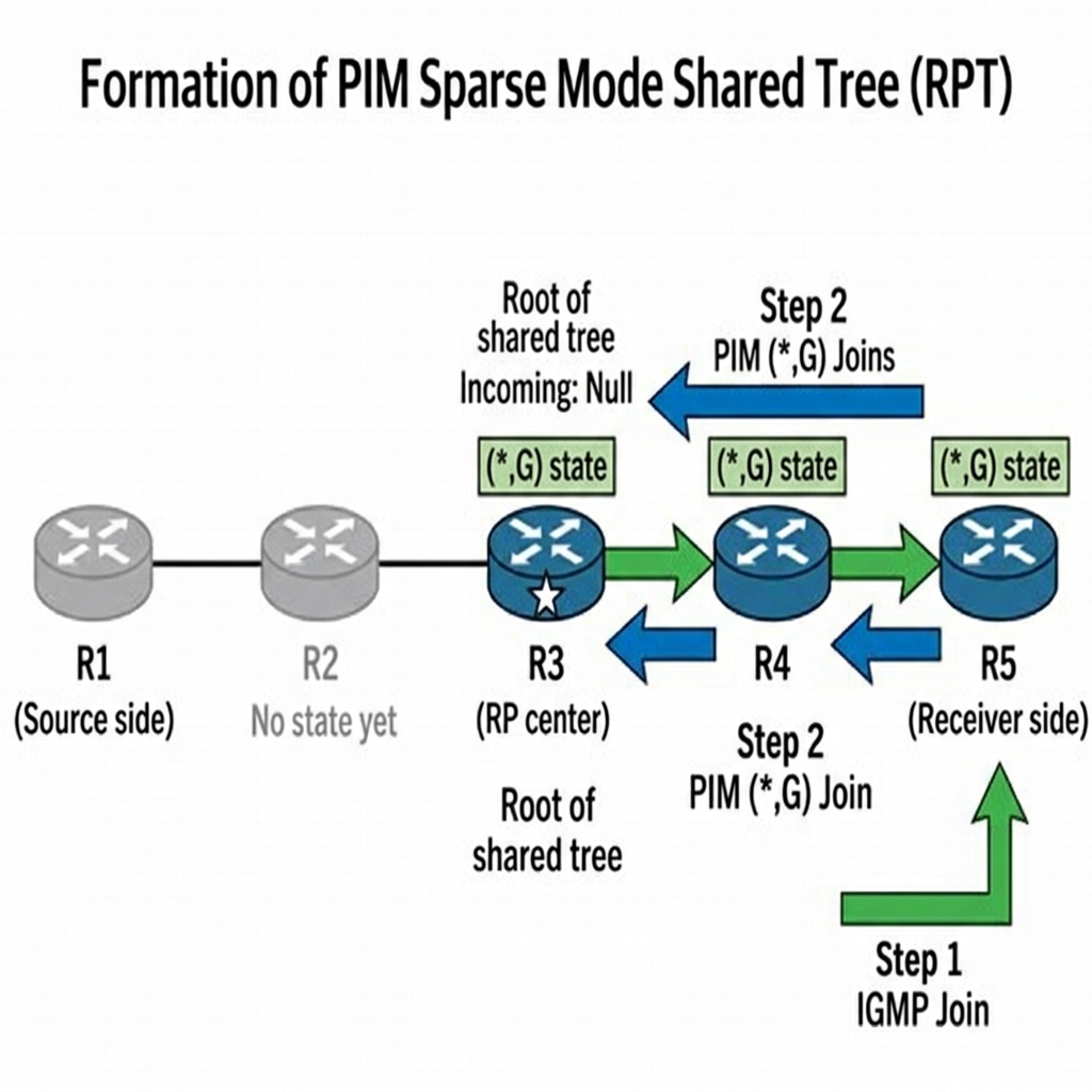
The Theory: In Sparse Mode, nothing flows until a receiver asks for it. When an end-host wants to receive a group, it sends an IGMP Membership Report to its gateway (the Last-Hop Router, R5). R5 then checks its unicast routing table to find the path toward the RP (3.3.3.3). It then sends a PIM (*, G) Join message upstream toward the RP. This builds the Shared Tree or RPT.
Let us have the receiver join group 239.1.1.1.
!! On Receiver — join group 239.1.1.1
Receiver(config)# interface GigabitEthernet0/0
Receiver(config-if)# ip igmp join-group 239.1.1.1
R5 receives the IGMP Report & needs to pull traffic for (*, 239.1.1.1) from the RP. It sends a PIM Join toward 3.3.3.3 (the RP).
R5# show ip mroute 239.1.1.1
Output:
(*, 239.1.1.1), 00:00:10/00:03:20, RP 3.3.3.3, flags: SJC
  Incoming interface: GigabitEthernet0/0, RPF nbr 10.45.0.4
  Outgoing interface list:
    GigabitEthernet0/1, Forward/Sparse, 00:00:10/00:03:20
R5 created a (*, 239.1.1.1) entry — any source for group 239.1.1.1. The incoming interface is Gi0/0 (toward R4), & the RPF neighbor is 10.45.0.4 (R4), because the path to the RP (3.3.3.3) goes through R4.
The PIM Join propagated to R4:
R4# show ip mroute 239.1.1.1
Output:
(*, 239.1.1.1), 00:00:08/00:03:22, RP 3.3.3.3, flags: S
  Incoming interface: GigabitEthernet0/0, RPF nbr 10.34.0.3
  Outgoing interface list:
    GigabitEthernet0/1, Forward/Sparse, 00:00:08/00:03:22
R4 forwards the Join toward R3 (the RP). And on R3:
R3# show ip mroute 239.1.1.1
Output:
(*, 239.1.1.1), 00:00:06/00:03:24, RP 3.3.3.3, flags: S
  Incoming interface: Null, RPF nbr 0.0.0.0
  Outgoing interface list:
    GigabitEthernet0/1, Forward/Sparse, 00:00:06/00:03:24
Notice that on R3 (the RP), the incoming interface is Null. This makes sense — R3 is the RP, so there is nowhere upstream to pull traffic from. It is the root of the shared tree. Traffic for any source will arrive here & be distributed down the tree.
The shared tree path is: R3 → R4 → R5 → Receiver. This is the RPT (Rendezvous Point Tree).
The Theory: Now imagine a source starts sending traffic. The first-hop router (R1) receives this multicast, but it doesn’t know where the receivers are (unlike Dense Mode, it won’t just flood it). Instead, R1 encapsulates the multicast packet inside a unicast PIM Register message and sends it directly to the RP. The RP then de-encapsulates it and forwards it down the shared tree we just built.
Let us start the multicast source using a continuous ping.
!! On Source — send multicast traffic
Source# ping 239.1.1.1 repeat 1000000 size 1000
Enable debug on R1 (the source’s first-hop router):
R1# debug ip pim
Output:
*Apr 19 01:25:10.100: PIM(0): Check RP 3.3.3.3 into the (*, 239.1.1.1) entry
*Apr 19 01:25:10.101: PIM(0): Send v2 Register to 3.3.3.3 for 10.0.0.10, group 239.1.1.1
*Apr 19 01:25:10.102: PIM(0): Building Register Header for 10.0.0.10, group 239.1.1.1
Here is what happened: R1 received multicast traffic from the Source on Gi0/0, but R1 has no (*, 239.1.1.1) state because nobody downstream of R1 has joined. In PIM Sparse Mode, R1 cannot just flood the traffic (that would be Dense Mode behavior). Instead, R1 encapsulates the first multicast packet inside a PIM Register message & unicasts it to the RP at 3.3.3.3.
Check R1’s mroute:
R1# show ip mroute 239.1.1.1
Output:
(10.0.0.10, 239.1.1.1), 00:00:05/00:02:55, flags: SPF
  Incoming interface: GigabitEthernet0/0, RPF nbr 0.0.0.0
  Outgoing interface list:
    GigabitEthernet0/1, Forward/Sparse, 00:00:05/00:02:55
The “F” flag means the Register flag is set — R1 is actively sending PIM Register messages to the RP.
Now check the RP (R3):
R3# show ip mroute 239.1.1.1
Output:
(*, 239.1.1.1), 00:02:00/00:03:00, RP 3.3.3.3, flags: S
  Incoming interface: Null, RPF nbr 0.0.0.0
  Outgoing interface list:
    GigabitEthernet0/1, Forward/Sparse, 00:02:00/00:03:00

(10.0.0.10, 239.1.1.1), 00:00:05/00:02:55, flags: ST
  Incoming interface: GigabitEthernet0/0, RPF nbr 10.23.0.2
  Outgoing interface list:
    GigabitEthernet0/1, Forward/Sparse, 00:00:05/00:02:55
R3 now has two entries:
1. (*, 239.1.1.1) — the shared tree entry from the receiver’s join
2. (10.0.0.10, 239.1.1.1) — a source-specific entry created when the Register arrived
R3 de-encapsulates the Register, examines the original multicast packet, & forwards it down the shared tree (out Gi0/1 toward R4, then R5, then the Receiver).
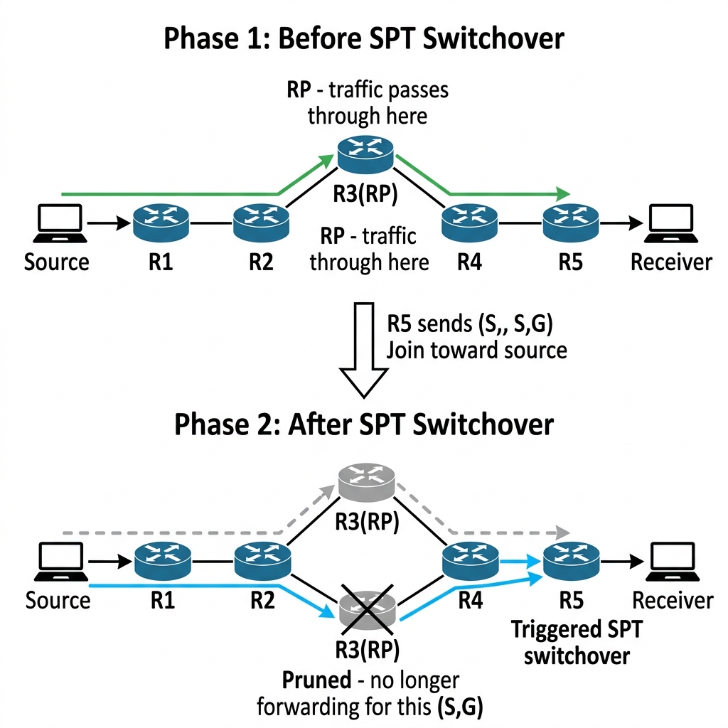
At this point, traffic is flowing, but it is taking the long path: Source → R1 → R2 → R3 (RP) → R4 → R5 → Receiver. That is 5 hops. The shortest path is R1 → R2 → R4 → R5, which is only 3 hops.
Step 4 — Phase 3: SPT Switchover
This is the most elegant part of PIM Sparse Mode. Once R5 starts receiving traffic through the shared tree, it knows the source address (10.0.0.10) from the data packets. R5 decides: “I can reach this source faster via the shortest path tree. Let me switch.”
By default on Cisco routers, the SPT switchover threshold is 0 kbps — meaning the last-hop router switches to SPT immediately after receiving the first packet from a particular source on the shared tree.
Watch R5’s mroute evolve:
R5# show ip mroute 239.1.1.1
Output (after a few seconds):
(*, 239.1.1.1), 00:03:00/00:03:00, RP 3.3.3.3, flags: SJC
  Incoming interface: GigabitEthernet0/0, RPF nbr 10.45.0.4
  Outgoing interface list:
    GigabitEthernet0/1, Forward/Sparse, 00:03:00/00:03:00

(10.0.0.10, 239.1.1.1), 00:00:15/00:02:45, flags: SJT
  Incoming interface: GigabitEthernet0/0, RPF nbr 10.45.0.4
  Outgoing interface list:
    GigabitEthernet0/1, Forward/Sparse, 00:00:15/00:02:45
R5 now has an (S,G) entry with the “J” flag — Join SPT. R5 sent a source-specific PIM Join directly toward 10.0.0.10 (the source), bypassing the RP. Let us trace the new path.
R4# show ip mroute 239.1.1.1
Output:
(10.0.0.10, 239.1.1.1), 00:00:12/00:02:48, flags: ST
  Incoming interface: GigabitEthernet0/2, RPF nbr 10.25.0.2
  Outgoing interface list:
    GigabitEthernet0/1, Forward/Sparse, 00:00:12/00:02:48
Look at R4’s incoming interface — it is now Gi0/2 (toward R2), NOT Gi0/0 (toward R3/RP). The traffic is coming directly from R2 via the 10.25.0.0/24 link. The SPT switchover worked — traffic is now taking the shortest path: Source → R1 → R2 → R4 → R5 → Receiver 43 hops instead of 5).
And on R3 (the RP), the source-specific entry should now show a prune:
R3# show ip mroute 239.1.1.1
Output:
(*, 239.1.1.1), 00:05:00/00:03:00, RP 3.3.3.3, flags: S
  Incoming interface: Null, RPF nbr 0.0.0.0
  Outgoing interface list:
    GigabitEthernet0/1, Forward/Sparse, 00:05:00/00:03:00

(10.0.0.10, 239.1.1.1), 00:02:00/00:01:00, flags: SPR
  Incoming interface: GigabitEthernet0/0, RPF nbr 10.23.0.2
  Outgoing interface list: Null
The “P” and “R” flags on R3’s (S,G) entry mean Pruned & RP-bit set. R4 sent an (S,G,RPT) Prune toward the RP, telling R3: “I am getting traffic directly from the source now, stop sending it to me via the shared tree for this particular source.”
Step 5 — Controlling SPT Switchover
You can control when the SPT switchover happens using the ip pim spt-threshold command.
!! Set SPT switchover threshold to infinity — NEVER switch to SPT
R5(config)# ip pim spt-threshold infinity

!! Or set a specific rate threshold (in kbps)
R5(config)# ip pim spt-threshold 100
With infinity, R5 will always use the shared tree through the RP. This is sometimes used in IPTV environments where you want to control traffic paths & keep everything flowing through the RP.
Let us verify after setting the threshold to infinity:
R5# show ip mroute 239.1.1.1
Output:
(*, 239.1.1.1), 00:06:00/00:03:00, RP 3.3.3.3, flags: SJC
  Incoming interface: GigabitEthernet0/0, RPF nbr 10.45.0.4
  Outgoing interface list:
    GigabitEthernet0/1, Forward/Sparse, 00:06:00/00:03:00
Only the (*, G) entry remains. R5 is not building any SPT — all traffic comes through the RP.
In production, the default behavior (spt-threshold 0) is usually fine. But in large IPTV deployments, setting spt-threshold infinity on the last-hop routers keeps traffic on the shared tree, which gives you centralized traffic engineering control through RP placement.
Step 6 — PIM Register Stop
One detail we glossed over: once the RP starts receiving traffic via the native multicast tree (not via Register messages), the RP sends a PIM Register-Stop to the source’s first-hop router (R1). This tells R1 to stop encapsulating traffic in Register messages the RP is now getting it natively.
R1# show ip mroute 239.1.1.1
Output (after Register-Stop):
(10.0.0.10, 239.1.1.1), 00:03:00/00:02:30, flags: ST
  Incoming interface: GigabitEthernet0/0, RPF nbr 0.0.0.0
  Outgoing interface list:
    GigabitEthernet0/1, Forward/Sparse, 00:03:00/00:02:30
The “F” flag (Register) is gone. R1 stopped encapsulating & is now forwarding natively through the multicast tree.
Break It — Remove the RP
Let us see what happens when the RP disappears from the network.
!! On R3 — shut the loopback (removes the RP address from OSPF)
R3(config)# interface Loopback0
R3(config-if)# shutdown
Wait for OSPF to converge (a few seconds):
R5# show ip pim rp mapping
Output:
PIM Group-to-RP Mappings
Group(s): 224.0.0.0/4
  RP: 3.3.3.3 (?), Static
    Uptime: 00:10:00, Expires: never
The static RP config is still there, but the route to 3.3.3.3 is now gone from the routing table:
R5# show ip route 3.3.3.3
% Network not in table
Now check the mroute:
R5# show ip mroute 239.1.1.1
Output:
(*, 239.1.1.1), 00:08:00/stopped, RP 3.3.3.3, flags: SJCR
  Incoming interface: Null, RPF nbr 0.0.0.0, RPF fail
  Outgoing interface list:
    GigabitEthernet0/1, Forward/Sparse, 00:08:00/00:03:00
RPF failure. R5 cannot build a path to the RP because there is no route to 3.3.3.3. Any new receiver joins will fail. However, existing (S,G) entries (SPT traffic) may continue working because those do not depend on the RP they are source-rooted.
This is a critical design point: if you have active (S,G) SPT state, losing the RP does not immediately kill existing flows. But new receivers cannot join & new sources cannot register. The network degrades over time as existing state expires.
Fix it:
R3(config)# interface Loopback0
R3(config-if)# no shutdown
Within seconds, OSPF re-advertises 3.3.3.3, & the multicast tree rebuilds.
Phase Summary — The Complete PIM-SM Lifecycle
| Phase | What Happens | State Created |
|---|---|---|
| 1. Receiver Joins | IGMP Report → Last-hop router sends PIM Join toward RP | (*, G) on all routers in RPT |
| 2. Source Registers | First-hop router encapsulates multicast in PIM Register → sends to RP | (S, G) on RP |
| 3. RP Forwards | RP de-encapsulates Register & forwards down the RPT | Traffic flows via RP |
| 4. RP Joins SPT to Source | RP sends PIM Join directly toward Source to get native multicast | (S, G) on transit routers from Source to RP |
| 5. Register Stop | RP sends Register-Stop to first-hop router | First-hop stops encapsulating |
| 6. SPT Switchover | Last-hop router sends PIM Join directly toward Source | (S, G) on SPT, (S, G, RPT) Prune toward RP |
Key Takeaways
- PIM Sparse Mode uses a pull model — traffic only flows where receivers have explicitly joined
- The RP is the meeting point — receivers join toward it, sources register with it
- PIM Register is the mechanism that gets source traffic to the RP when no native tree exists
- SPT switchover is the optimization that bypasses the RP for better performance — default threshold is 0 (immediate)
(*, G)entries represent the shared tree (RPT) — any source, specific group(S, G)entries represent the shortest path tree (SPT) — specific source, specific group- Losing the RP does not immediately kill existing SPT flows, but prevents new joins & registrations