If you have been following this series, you now understand multicast deeply at a campus & enterprise level. Now let us talk about where multicast takes on a completely different role — the Data Center. In a modern DC fabric running VXLAN, multicast is not about delivering IPTV streams to end users. It is about replicating BUM traffic (Broadcast, Unknown Unicast, Multicast) in the VXLAN underlay so that VTEPs can discover each other & forward L2 traffic across an L3 routed spine.
I have to be honest — the industry has largely moved toward Ingress Replication (also called “head-end replication”) & EVPN for this job. But understanding the multicast underlay model is critical because (a) many existing fabrics still run it, (b) Nexus 9000 deployments in the field use it, & (c) the CCIE DC exam absolutely covers it. Plus, understanding why the industry moved away from multicast underlay teaches you important design tradeoffs.
What You Will Need
For this lab, we are using IOSv to approximate the VXLAN concepts. The commands differ slightly from Nexus 9000v, but the multicast underlay mechanics are identical.
| Component | Quantity | EVE-NG Image |
|---|---|---|
| Cisco IOSv Router (Network) | 5 | i86bi_Linux-L3-AdvEnterpriseK9-M2_157_3_May_2018.bin |
| Cisco IOSv Router (Hosts) | 3 | i86bi_Linux-L3-AdvEnterpriseK9-M2_157_3_May_2018.bin |
Total RAM required: approximately 4 GB.
Lab Topology
We are building a classic Spine-Leaf fabric. Two Spines provide the routed underlay, three Leaves serve as VTEPs.
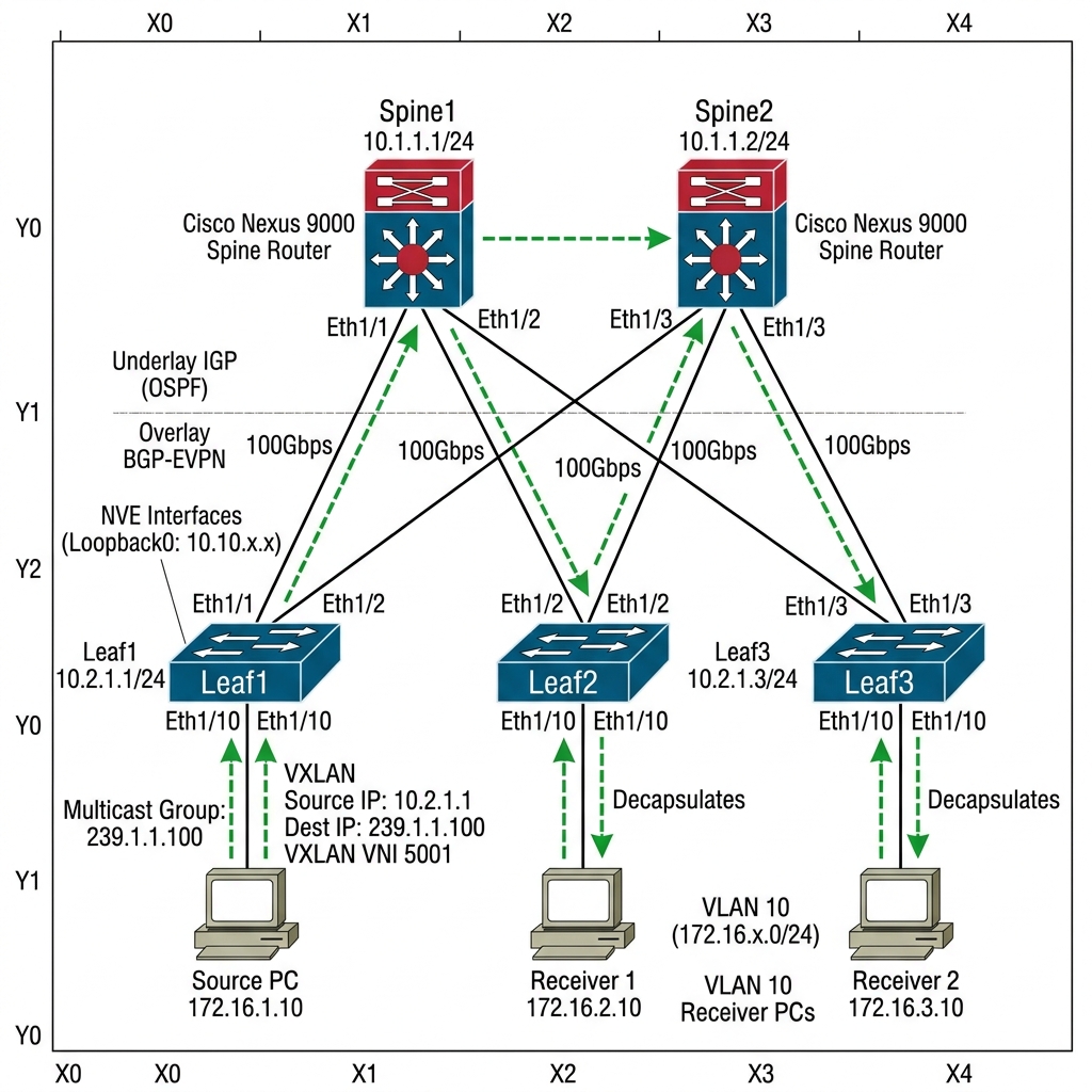
Simplified: Each Leaf connects to both Spines. Spine1 has the RP for the multicast underlay.
IP Addressing Table
| Device | Interface | IP Address | Description |
|---|---|---|---|
| Spine1 | Loopback0 | 10.10.10.10/32 | RID & RP |
| Spine1 | Gi0/1 | 172.16.1.1/30 | To Leaf1 |
| Spine1 | Gi0/2 | 172.16.2.1/30 | To Leaf2 |
| Spine1 | Gi0/3 | 172.16.3.1/30 | To Leaf3 |
| Spine2 | Loopback0 | 20.20.20.20/32 | RID |
| Spine2 | Gi0/1 | 172.16.11.1/30 | To Leaf1 |
| Spine2 | Gi0/2 | 172.16.12.1/30 | To Leaf2 |
| Spine2 | Gi0/3 | 172.16.13.1/30 | To Leaf3 |
| Leaf1 | Loopback0 | 1.1.1.1/32 | VTEP source |
| Leaf1 | Gi0/1 | 172.16.1.2/30 | To Spine1 |
| Leaf1 | Gi0/2 | 172.16.11.2/30 | To Spine2 |
| Leaf1 | Gi0/3 | 10.100.1.1/24 | To Host1 (VLAN 100) |
| Leaf2 | Loopback0 | 2.2.2.2/32 | VTEP source |
| Leaf2 | Gi0/1 | 172.16.2.2/30 | To Spine1 |
| Leaf2 | Gi0/2 | 172.16.12.2/30 | To Spine2 |
| Leaf2 | Gi0/3 | 10.100.1.2/24 | To Host2 (VLAN 100) |
| Leaf3 | Loopback0 | 3.3.3.3/32 | VTEP source |
| Leaf3 | Gi0/1 | 172.16.3.2/30 | To Spine1 |
| Leaf3 | Gi0/2 | 172.16.13.2/30 | To Spine2 |
| Leaf3 | Gi0/3 | 10.100.1.3/24 | To Host3 (VLAN 100) |
Step 1 — OSPF Underlay Configuration
Every device runs OSPF in the underlay. All links are point-to-point.
Spine1 Configuration:
hostname Spine1
!
interface Loopback0
 ip address 10.10.10.10 255.255.255.255
 ip pim sparse-mode
 ip ospf 1 area 0
!
interface GigabitEthernet0/1
 ip address 172.16.1.1 255.255.255.252
 ip pim sparse-mode
 ip ospf 1 area 0
 ip ospf network point-to-point
 no shutdown
!
interface GigabitEthernet0/2
 ip address 172.16.2.1 255.255.255.252
 ip pim sparse-mode
 ip ospf 1 area 0
 ip ospf network point-to-point
 no shutdown
!
interface GigabitEthernet0/3
 ip address 172.16.3.1 255.255.255.252
 ip pim sparse-mode
 ip ospf 1 area 0
 ip ospf network point-to-point
 no shutdown
!
router ospf 1
 router-id 10.10.10.10
!
ip multicast-routing
ip pim rp-address 10.10.10.10
Spine2 Configuration:
hostname Spine2
!
interface Loopback0
 ip address 20.20.20.20 255.255.255.255
 ip pim sparse-mode
 ip ospf 1 area 0
!
interface GigabitEthernet0/1
 ip address 172.16.11.1 255.255.255.252
 ip pim sparse-mode
 ip ospf 1 area 0
 ip ospf network point-to-point
 no shutdown
!
interface GigabitEthernet0/2
 ip address 172.16.12.1 255.255.255.252
 ip pim sparse-mode
 ip ospf 1 area 0
 ip ospf network point-to-point
 no shutdown
!
interface GigabitEthernet0/3
 ip address 172.16.13.1 255.255.255.252
 ip pim sparse-mode
 ip ospf 1 area 0
 ip ospf network point-to-point
 no shutdown
!
router ospf 1
 router-id 20.20.20.20
!
ip multicast-routing
ip pim rp-address 10.10.10.10
Leaf1 Configuration (similar for Leaf2/Leaf3, adjust IPs):
hostname Leaf1
!
interface Loopback0
 ip address 1.1.1.1 255.255.255.255
 ip pim sparse-mode
 ip ospf 1 area 0
!
interface GigabitEthernet0/1
 ip address 172.16.1.2 255.255.255.252
 ip pim sparse-mode
 ip ospf 1 area 0
 ip ospf network point-to-point
 no shutdown
!
interface GigabitEthernet0/2
 ip address 172.16.11.2 255.255.255.252
 ip pim sparse-mode
 ip ospf 1 area 0
 ip ospf network point-to-point
 no shutdown
!
interface GigabitEthernet0/3
 ip address 10.100.1.1 255.255.255.0
 no shutdown
!
router ospf 1
 router-id 1.1.1.1
!
ip multicast-routing
ip pim rp-address 10.10.10.10
Leaf2 Configuration:
hostname Leaf2
!
interface Loopback0
 ip address 2.2.2.2 255.255.255.255
 ip pim sparse-mode
 ip ospf 1 area 0
!
interface GigabitEthernet0/1
 ip address 172.16.2.2 255.255.255.252
 ip pim sparse-mode
 ip ospf 1 area 0
 ip ospf network point-to-point
 no shutdown
!
interface GigabitEthernet0/2
 ip address 172.16.12.2 255.255.255.252
 ip pim sparse-mode
 ip ospf 1 area 0
 ip ospf network point-to-point
 no shutdown
!
interface GigabitEthernet0/3
 ip address 10.100.1.2 255.255.255.0
 no shutdown
!
router ospf 1
 router-id 2.2.2.2
!
ip multicast-routing
ip pim rp-address 10.10.10.10
Leaf3 Configuration:
hostname Leaf3
!
interface Loopback0
 ip address 3.3.3.3 255.255.255.255
 ip pim sparse-mode
 ip ospf 1 area 0
!
interface GigabitEthernet0/1
 ip address 172.16.3.2 255.255.255.252
 ip pim sparse-mode
 ip ospf 1 area 0
 ip ospf network point-to-point
 no shutdown
!
interface GigabitEthernet0/2
 ip address 172.16.13.2 255.255.255.252
 ip pim sparse-mode
 ip ospf 1 area 0
 ip ospf network point-to-point
 no shutdown
!
interface GigabitEthernet0/3
 ip address 10.100.1.3 255.255.255.0
 no shutdown
!
ip multicast-routing
ip pim rp-address 10.10.10.10
Host Configuration (Cisco Routers):
We configure these as simple L2 hosts connecting to the Leaves.
!! Host 1 config (repeat for Host 2 & 3 with their IPs)
hostname Host1
no ip routing
interface GigabitEthernet0/0
 ip address 10.100.1.11 255.255.255.0
 no shutdown
ip default-gateway 10.100.1.1
Step 2 — Verify Underlay & PIM
Spine1# show ip pim neighbor
Output:
PIM Neighbor Table
Neighbor          Interface                Uptime/Expires    Ver   DR
172.16.1.2        GigabitEthernet0/1       00:05:00/00:01:30 v2    1 / S P G
172.16.2.2        GigabitEthernet0/2       00:05:00/00:01:28 v2    1 / S P G
172.16.3.2        GigabitEthernet0/3       00:05:00/00:01:32 v2    1 / S P G
All three Leaves are PIM neighbors of Spine1. Good.
Step 3 — VXLAN Configuration (Conceptual)
On actual Nexus 9000v or NX-OS, VXLAN with multicast underlay would look like this:
!! NX-OS style VXLAN config (for reference)
feature nv overlay
feature vn-segment-vlan-based

vlan 100
  vn-segment 10100

interface nve1
  no shutdown
  source-interface loopback0
  member vni 10100
    mcast-group 239.1.1.100
The key line is mcast-group 239.1.1.100. This tells the VTEP: “For BUM traffic in VNI 10100, send it to multicast group 239.1.1.100 in the underlay.” Every VTEP that has VNI 10100 joins this group via IGMP, & PIM-SM builds a tree in the underlay to deliver the BUM traffic.
On IOSv, we can simulate this concept by having each Leaf join the multicast group 239.1.1.100:
!! On each Leaf — simulate VTEP joining the VXLAN multicast group
!! In production, NVE does this automatically
Leaf1(config)# interface GigabitEthernet0/3
Leaf1(config-if)# ip igmp join-group 239.1.1.100
Repeat on Leaf2 & Leaf3.
Step 4 — Verify the Multicast Underlay Tree
Spine1# show ip mroute 239.1.1.100
Output:
(*, 239.1.1.100), 00:01:00/00:03:00, RP 10.10.10.10, flags: S
  Incoming interface: Null, RPF nbr 0.0.0.0
  Outgoing interface list:
    GigabitEthernet0/1, Forward/Sparse, 00:01:00/00:03:00
    GigabitEthernet0/2, Forward/Sparse, 00:00:58/00:03:02
    GigabitEthernet0/3, Forward/Sparse, 00:00:55/00:03:05
Spine1 (the RP) has all three Leaf interfaces in the outgoing list for 239.1.1.100. When any VTEP sends BUM traffic, it gets encapsulated in a VXLAN outer header with destination 239.1.1.100. The underlay PIM tree delivers it to all other VTEPs.
The Theory: When Host1 sends a frame destined for a MAC address it doesn’t know (or a broadcast ARP), Leaf1 encapsulates that frame into a VXLAN packet. Instead of sending it to a specific VTEP, it sends it to the Underlay Multicast Group (239.1.1.100). The Spine routers then replicate this packet to every other Leaf that has joined that group.
Let us simulate this by sending a multicast ping from Host1.
!! From Host1 — send traffic to the multicast group
Host1# ping 239.1.1.100 repeat 10
Check that the traffic reaches all Leaves:
Leaf2# show ip mroute 239.1.1.100 count
Output:
Group: 239.1.1.100, Source count: 1, Packets forwarded: 10, Packets received: 10
All Leaves receive the BUM traffic via the multicast underlay.
Step 6 — Ingress Replication vs Multicast Underlay
Now let us understand the alternative — Ingress Replication (also called Head-End Replication). Instead of using multicast, each VTEP unicasts a copy of the BUM frame to every other VTEP in the VNI.
| Characteristic | Multicast Underlay | Ingress Replication |
|---|---|---|
| Underlay Requirement | PIM-SM + RP | None — pure unicast |
| Spine State | (S,G) & (*,G) mroute entries per VNI group | None |
| Bandwidth Usage | Efficient — 1 copy per link | N copies per VTEP (N-1 unicast) |
| Scalability | Limited by multicast state on spines | Limited by VTEP replication capacity |
| Complexity | High — PIM troubleshooting in underlay | Low — no multicast to manage |
| Modern Preference | Legacy/existing deployments | Industry default (with EVPN) |
The industry moved to ingress replication + EVPN because the operational complexity of maintaining PIM in the underlay was not worth the bandwidth savings in most DC environments. With EVPN, VTEPs learn remote MAC addresses via BGP, & BUM replication uses ingress replication — no multicast needed.
However, in very large-scale DC environments (1000+ VTEPs per VNI), multicast underlay may still be more efficient than ingress replication.
Break It — Remove PIM from One Spine Uplink
!! On Spine1 — remove PIM from the link to Leaf3
Spine1(config)# interface GigabitEthernet0/3
Spine1(config-if)# no ip pim sparse-mode
Spine1# show ip mroute 239.1.1.100
Output:
(*, 239.1.1.100), 00:05:00/00:03:00, RP 10.10.10.10, flags: S
  Incoming interface: Null, RPF nbr 0.0.0.0
  Outgoing interface list:
    GigabitEthernet0/1, Forward/Sparse, 00:05:00/00:03:00
    GigabitEthernet0/2, Forward/Sparse, 00:04:58/00:03:02
Leaf3 is gone from the outgoing list. BUM traffic no longer reaches Leaf3. Any VMs behind Leaf3 cannot communicate with VMs behind Leaf1 or Leaf2 via L2. ARP breaks, DHCP breaks, everything on that VXLAN segment behind Leaf3 goes dark.
The fix is obvious:
Spine1(config)# interface GigabitEthernet0/3
Spine1(config-if)# ip pim sparse-mode
In production DC fabrics, this is why many teams prefer ingress replication — one missing ip pim sparse-mode on a spine uplink can take down an entire rack’s VXLAN connectivity. With ingress replication, there is no PIM to forget.
Key Takeaways
- VXLAN can use multicast in the underlay to replicate BUM traffic across VTEPs
- Each VNI maps to a multicast group — VTEPs join the group, & PIM-SM builds the replication tree
- The RP runs on the spine — it is the root of the multicast tree for VXLAN BUM traffic
- Ingress replication is the modern alternative — simpler, no PIM needed, preferred with EVPN
- Multicast underlay is still used in legacy Nexus 9000 deployments & high-scale environments
- Missing PIM on a spine link kills VXLAN connectivity for the entire downstream rack
- EVPN + Ingress Replication has largely replaced multicast underlay in new deployments