This is the capstone. If you have worked through the previous articles, you now know how every multicast protocol operates at the packet level. You can configure PIM, troubleshoot RPF failures, & set up any RP mechanism. But knowing how the protocols work is not the same as knowing how to design a multicast network that scales, stays secure, & does not collapse when someone plugs in a rogue source. That is what we are going to build in this article.
What You Will Need
| Component | Quantity | EVE-NG Image |
|---|---|---|
| Cisco IOSv Router (Network) | 8 | i86bi_Linux-L3-AdvEnterpriseK9-M2_157_3_May_2018.bin |
| Cisco IOSv Router (Source/Receiver) | 4 | i86bi_Linux-L3-AdvEnterpriseK9-M2_157_3_May_2018.bin |
Total RAM required: approximately 6 GB. This is the largest lab in the series.
Lab Topology
We are building a multi-area OSPF network that represents a realistic enterprise. Three areas: Area 0 (core with RPs), Area 1 (campus with receivers), Area 2 (source farm / data center).
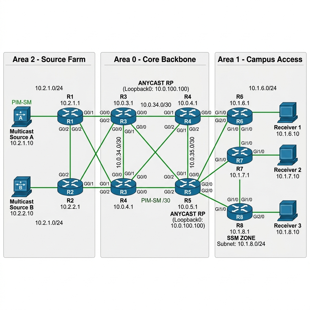
IP Addressing Table
| Device | Interface | IP Address | Area | Description |
|---|---|---|---|---|
| R1 | Gi0/0 | 10.0.0.1/24 | 2 | To Source1 |
| R1 | Gi0/1 | 10.12.0.1/24 | 2 | To R2 |
| R1 | Gi0/2 | 10.13.0.1/24 | 0 | To R3 (ABR link) |
| R2 | Gi0/0 | 10.6.0.1/24 | 2 | To Source2 |
| R2 | Gi0/1 | 10.12.0.2/24 | 2 | To R1 |
| R2 | Gi0/2 | 10.25.0.2/24 | 0 | To R5 (ABR link) |
| R3 | Gi0/0 | 10.13.0.3/24 | 0 | To R1 |
| R3 | Gi0/1 | 10.34.0.3/24 | 0 | To R4 |
| R3 | Gi0/2 | 10.35.0.3/24 | 0 | To R5 |
| R3 | Lo0 | 3.3.3.3/32 | 0 | Router ID |
| R3 | Lo1 | 10.10.10.10/32 | 0 | Anycast RP (shared) |
| R4 | Gi0/0 | 10.34.0.4/24 | 0 | To R3 |
| R4 | Gi0/1 | 10.46.0.4/24 | 1 | To R6 (ABR link) |
| R4 | Gi0/2 | 10.47.0.4/24 | 1 | To R7 (ABR link) |
| R5 | Gi0/0 | 10.35.0.5/24 | 0 | To R3 |
| R5 | Gi0/1 | 10.25.0.5/24 | 0 | To R2 |
| R5 | Gi0/2 | 10.58.0.5/24 | 1 | To R8 (ABR link) |
| R5 | Lo0 | 5.5.5.5/32 | 0 | Router ID |
| R5 | Lo1 | 10.10.10.10/32 | 0 | Anycast RP (shared) |
| R6 | Gi0/0 | 10.46.0.6/24 | 1 | To R4 |
| R6 | Gi0/1 | 10.60.0.1/24 | 1 | To Receiver1 |
| R7 | Gi0/0 | 10.47.0.7/24 | 1 | To R4 |
| R7 | Gi0/1 | 10.70.0.1/24 | 1 | To Receiver2 |
| R8 | Gi0/0 | 10.58.0.8/24 | 1 | To R5 |
| R8 | Gi0/1 | 10.80.0.1/24 | 1 | To SSM Receiver |
| Source1 | Gi0/0 | 10.0.0.10/24 | 2 | Multicast Source 1 |
| Source2 | Gi0/0 | 10.6.0.10/24 | 2 | Multicast Source 2 |
| Receiver1 | Gi0/0 | 10.60.0.10/24 | 1 | Multicast Receiver 1 |
| SSM_Recv | Gi0/0 | 10.80.0.10/24 | 1 | SSM Multicast Receiver |
| — |
Step 1 — Multi-Area OSPF Underlay
The OSPF underlay is the foundation. We need every router to reach every Loopback (especially the Anycast RP Loopback 10.10.10.10). Without routing, there is no multicast.
R1 Configuration:
hostname R1
!
!! The Loopback gives R1 a stable router-id that never goes down
!! even if physical interfaces flap — essential for OSPF stability
interface Loopback0
 ip address 1.1.1.1 255.255.255.255
!
!! Gi0/0 faces the Source1 host — this is the multicast entry point
!! We put it in Area 2 because all sources live in the "source farm" area
interface GigabitEthernet0/0
 ip address 10.0.0.1 255.255.255.0
 no shutdown
!
!! Gi0/1 connects to R2 — both source-side routers peer within Area 2
!! so that source subnets stay intra-area (faster convergence)
interface GigabitEthernet0/1
 ip address 10.12.0.1 255.255.255.0
 no shutdown
!
!! Gi0/2 is the ABR link into Area 0 (the core)
!! This is where Area 2 source routes get summarized into the backbone
interface GigabitEthernet0/2
 ip address 10.13.0.1 255.255.255.0
 no shutdown
!
!! OSPF config — R1 is an ABR because it has interfaces in both Area 0 & Area 2
!! The 'network' statements place each interface into the correct area
router ospf 1
 router-id 1.1.1.1
 network 1.1.1.1 0.0.0.0 area 2
 network 10.0.0.0 0.0.0.255 area 2
 network 10.12.0.0 0.0.0.255 area 2
 network 10.13.0.0 0.0.0.255 area 0
R2 Configuration:
hostname R2
!
interface Loopback0
 ip address 2.2.2.2 255.255.255.255
!
!! Gi0/0 faces Source2 — second multicast source in the farm
interface GigabitEthernet0/0
 ip address 10.6.0.1 255.255.255.0
 no shutdown
!
!! Gi0/1 peers with R1 within Area 2
interface GigabitEthernet0/1
 ip address 10.12.0.2 255.255.255.0
 no shutdown
!
!! Gi0/2 is R2's ABR link into the core via R5
!! This gives us two entry points from Area 2 into Area 0 (redundancy)
interface GigabitEthernet0/2
 ip address 10.25.0.2 255.255.255.0
 no shutdown
!
router ospf 1
 router-id 2.2.2.2
 network 2.2.2.2 0.0.0.0 area 2
 network 10.6.0.0 0.0.0.255 area 2
 network 10.12.0.0 0.0.0.255 area 2
 network 10.25.0.0 0.0.0.255 area 0
R3 Configuration (Core + Anycast RP):
hostname R3
!
!! Lo0 is the unique router-id — used for MSDP peering
!! NOT the Anycast RP address (that is on Lo1)
interface Loopback0
 ip address 3.3.3.3 255.255.255.255
!
!! Lo1 is the ANYCAST RP address — 10.10.10.10
!! BOTH R3 & R5 share this same IP. When both are up, routers
!! pick the closest RP via OSPF metric. If one dies, OSPF
!! reconverges & everyone shifts to the survivor. This is
!! the gold standard for RP redundancy.
interface Loopback1
 ip address 10.10.10.10 255.255.255.255
!
!! Gi0/0 connects to R1 — the ABR link from the source farm
interface GigabitEthernet0/0
 ip address 10.13.0.3 255.255.255.0
 no shutdown
!
!! Gi0/1 & Gi0/2 connect to R4 & R5 within the core
!! This gives us a full-mesh core for redundancy
interface GigabitEthernet0/1
 ip address 10.34.0.3 255.255.255.0
 no shutdown
!
interface GigabitEthernet0/2
 ip address 10.35.0.3 255.255.255.0
 no shutdown
!
!! Everything in Area 0 — R3 is a pure backbone router
router ospf 1
 router-id 3.3.3.3
 network 3.3.3.3 0.0.0.0 area 0
 network 10.10.10.10 0.0.0.0 area 0
 network 10.13.0.0 0.0.0.255 area 0
 network 10.34.0.0 0.0.0.255 area 0
 network 10.35.0.0 0.0.0.255 area 0
R4 Configuration (Core ABR into Campus):
hostname R4
!
interface Loopback0
 ip address 4.4.4.4 255.255.255.255
!
!! Gi0/0 connects to R3 in the core
interface GigabitEthernet0/0
 ip address 10.34.0.4 255.255.255.0
 no shutdown
!
!! Gi0/1 & Gi0/2 are ABR links into the campus (Area 1)
!! R4 serves as the gateway for R6 & R7's receiver subnets
interface GigabitEthernet0/1
 ip address 10.46.0.4 255.255.255.0
 no shutdown
!
interface GigabitEthernet0/2
 ip address 10.47.0.4 255.255.255.0
 no shutdown
!
router ospf 1
 router-id 4.4.4.4
 network 4.4.4.4 0.0.0.0 area 0
 network 10.34.0.0 0.0.0.255 area 0
 network 10.46.0.0 0.0.0.255 area 1
 network 10.47.0.0 0.0.0.255 area 1
R5 Configuration (Core + Second Anycast RP):
hostname R5
!
!! Lo0 is unique — used for MSDP peering with R3
interface Loopback0
 ip address 5.5.5.5 255.255.255.255
!
!! Lo1 shares the SAME Anycast RP IP as R3
!! Both R3 & R5 advertise 10.10.10.10/32 via OSPF
!! Routers closest to R3 use R3 as RP; those closest to R5 use R5
interface Loopback1
 ip address 10.10.10.10 255.255.255.255
!
interface GigabitEthernet0/0
 ip address 10.35.0.5 255.255.255.0
 no shutdown
!
interface GigabitEthernet0/1
 ip address 10.25.0.5 255.255.255.0
 no shutdown
!
!! Gi0/2 is R5's ABR link into the campus for R8 (SSM zone)
interface GigabitEthernet0/2
 ip address 10.58.0.5 255.255.255.0
 no shutdown
!
router ospf 1
 router-id 5.5.5.5
 network 5.5.5.5 0.0.0.0 area 0
 network 10.10.10.10 0.0.0.0 area 0
 network 10.35.0.0 0.0.0.255 area 0
 network 10.25.0.0 0.0.0.255 area 0
 network 10.58.0.0 0.0.0.255 area 1
R6 Configuration (Campus — ASM Receiver):
hostname R6
!
interface Loopback0
 ip address 6.6.6.6 255.255.255.255
!
!! Gi0/0 is the uplink to the core via R4
interface GigabitEthernet0/0
 ip address 10.46.0.6 255.255.255.0
 no shutdown
!
!! Gi0/1 faces the receiver LAN — this is where IGMP runs
!! and where multicast traffic gets delivered to end hosts
interface GigabitEthernet0/1
 ip address 10.60.0.1 255.255.255.0
 no shutdown
!
router ospf 1
 router-id 6.6.6.6
 network 6.6.6.6 0.0.0.0 area 1
 network 10.46.0.0 0.0.0.255 area 1
 network 10.60.0.0 0.0.0.255 area 1
R7 Configuration (Campus — ASM Receiver):
hostname R7
!
interface Loopback0
 ip address 7.7.7.7 255.255.255.255
!
interface GigabitEthernet0/0
 ip address 10.47.0.7 255.255.255.0
 no shutdown
!
interface GigabitEthernet0/1
 ip address 10.70.0.1 255.255.255.0
 no shutdown
!
router ospf 1
 router-id 7.7.7.7
 network 7.7.7.7 0.0.0.0 area 1
 network 10.47.0.0 0.0.0.255 area 1
 network 10.70.0.0 0.0.0.255 area 1
R8 Configuration (Campus — SSM Zone):
hostname R8
!
interface Loopback0
 ip address 8.8.8.8 255.255.255.255
!
interface GigabitEthernet0/0
 ip address 10.58.0.8 255.255.255.0
 no shutdown
!
!! Gi0/1 is the SSM receiver LAN — we will configure IGMPv3
!! here because SSM requires source-specific joins
interface GigabitEthernet0/1
 ip address 10.80.0.1 255.255.255.0
 no shutdown
!
router ospf 1
  router-id 8.8.8.8
  network 8.8.8.8 0.0.0.0 area 1
  network 10.58.0.0 0.0.0.255 area 1
  network 10.80.0.0 0.0.0.255 area 1
!
**Source & Receiver Configuration (Cisco Routers):**

We set these up as simple L2 hosts.
!! Source1 config (Repeat for Source2)
hostname Source1
no ip routing
interface GigabitEthernet0/0
ip address 10.0.0.10 255.255.255.0
no shutdown
ip default-gateway 10.0.0.1
!! Receiver1 config (Repeat for Receiver2)
hostname Receiver1
no ip routing
interface GigabitEthernet0/0
ip address 10.60.0.10 255.255.255.0
no shutdown
ip default-gateway 10.60.0.1
!! SSM Receiver config
hostname SSM_Recv
no ip routing
interface GigabitEthernet0/0
ip address 10.80.0.10 255.255.255.0
no shutdown
ip default-gateway 10.80.0.1
Verify OSPF adjacencies from the core:
R3# show ip ospf neighbor
**Output:**
Neighbor ID Pri State Dead Time Address Interface
1.1.1.1 1 FULL/DR 00:00:33 10.13.0.1 GigabitEthernet0/0
4.4.4.4 1 FULL/DR 00:00:31 10.34.0.4 GigabitEthernet0/1
5.5.5.5 1 FULL/DR 00:00:35 10.35.0.5 GigabitEthernet0/2
Verify all routers can reach the Anycast RP:
R6# show ip route 10.10.10.10
**Output:**
Routing entry for 10.10.10.10/32
Known via “ospf 1”, distance 110, metric 3, type inter area
Routing Descriptor Blocks:
* 10.46.0.4, from 4.4.4.4, via GigabitEthernet0/0
---

##### Step 2 — PIM Sparse Mode + Anycast RP with MSDP

Now we layer multicast on top of the OSPF underlay.

**On ALL routers (R1 through R8):**
!! This is the global switch that enables multicast routing
!! Without this, the router ignores all PIM & IGMP messages entirely
ip multicast-routing
!! Point every router to the Anycast RP address
!! Since both R3 & R5 own 10.10.10.10, each router picks the closest one
ip pim rp-address 10.10.10.10
**On ALL routers — enable PIM on every interface:**
!! PIM sparse-mode must be enabled on EVERY routed interface
!! that multicast traffic might transit through. Missing it on
!! even one interface breaks the tree at that point.
!! The Loopbacks need it too — especially the RP Loopbacks
!! because PIM Register messages are sourced from/to Loopbacks
interface Loopback0
ip pim sparse-mode
!
interface Loopback1
ip pim sparse-mode
!
interface GigabitEthernet0/0
ip pim sparse-mode
!
interface GigabitEthernet0/1
ip pim sparse-mode
!
interface GigabitEthernet0/2
ip pim sparse-mode
**R3 & R5 — MSDP Peering (Anycast RP synchronization):**
!! On R3 — MSDP peers with R5 using their UNIQUE Loopback0 addresses
!! NOT the shared Anycast Loopback1. MSDP needs distinct endpoints.
!! When a source registers with R3, R3 forwards a Source-Active (SA)
!! message to R5 via MSDP so R5 also knows about the source.
!! This ensures receivers behind R5 can reach sources that registered
!! with R3, and vice versa.
R3(config)# ip msdp peer 5.5.5.5 connect-source Loopback0
!! originator-id tells MSDP which address to use as the RP
!! in SA messages. Must be the unique Loopback, not the Anycast one.
R3(config)# ip msdp originator-id Loopback0
!! On R5 — mirror MSDP config pointing back to R3
R5(config)# ip msdp peer 3.3.3.3 connect-source Loopback0
R5(config)# ip msdp originator-id Loopback0
Verify MSDP peering:
R3# show ip msdp peer
**Output:**
MSDP Peer 5.5.5.5 (?), AS ?
Connection status:
State: Up, Resets: 0, Connection source: Loopback0 (3.3.3.3)
Uptime(Downtime): 00:02:30, Messages sent/received: 5/5
---

##### Step 3 — PIM Domain Boundaries

In a well-designed network, you do not let multicast leak everywhere. The `ip multicast boundary` command creates a hard wall — multicast traffic for specified groups cannot cross that interface.
!! On R4 — create a boundary that prevents the 239.100.x.x range
!! from leaving the campus (Area 1). This is “campus-only” multicast
!! — digital signage, building automation, etc. that should never
!! leak into the core or the source farm.
R4(config)# ip access-list standard CAMPUS_ONLY_MCAST
R4(config-std-nacl)# permit 239.100.0.0 0.0.255.255
!! Apply the boundary on the uplink toward the core
!! “filter-autorp” also blocks Auto-RP messages for these groups
!! so that RP advertisements for campus-only groups do not propagate
R4(config)# interface GigabitEthernet0/0
R4(config-if)# ip multicast boundary CAMPUS_ONLY_MCAST filter-autorp
!! Same boundary on R5’s uplink to prevent campus-only multicast
!! from leaking through the R5 path into the core
R5(config)# ip access-list standard CAMPUS_ONLY_MCAST
R5(config-std-nacl)# permit 239.100.0.0 0.0.255.255
!
R5(config)# interface GigabitEthernet0/0
R5(config-if)# ip multicast boundary CAMPUS_ONLY_MCAST filter-autorp
Verify:
R4# show ip pim interface GigabitEthernet0/0 | include boundary
**Output:**
Multicast boundary: CAMPUS_ONLY_MCAST (filtering)
Now if someone behind R6 or R7 creates a multicast stream on 239.100.1.1, it stays within the campus. It never reaches the core or the source farm.

---

##### Step 4 — Source Specific Multicast (SSM) on R8

SSM eliminates the RP entirely for specific groups. The receiver says: "I want group 232.1.1.1 from source 10.0.0.10" using IGMPv3. The router builds an (S,G) tree directly to the source — no shared tree, no RP involvement.
!! On R8 — configure IGMPv3 on the receiver-facing interface
!! IGMPv3 is REQUIRED for SSM because the receiver must specify
!! the source address in its join. IGMPv2 cannot do this.
R8(config)# interface GigabitEthernet0/1
R8(config-if)# ip igmp version 3
!! Define the SSM range globally — 232.0.0.0/8 is the IANA-assigned
!! range for SSM. Any group in this range automatically uses SSM
!! behavior (no RP lookup, direct source tree only)
R8(config)# ip pim ssm range 1
R8(config)# access-list 1 permit 232.0.0.0 0.255.255.255
!! The SSM range should also be configured on upstream routers
!! so they know not to do RP lookups for 232.x.x.x groups
!! Apply on R5 as well since it is R8’s upstream router
R5(config)# ip pim ssm range 1
R5(config)# access-list 1 permit 232.0.0.0 0.255.255.255
Test SSM from the receiver:

```bash
**The Theory:** Before you test SSM, remember that IGMPv3 is what makes it tick. The receiver must explicitly state the source it wants. In Cisco IOS, this is done using the `include` keyword in the join-group command.
!! On SSM_Recv — join 232.1.1.1 from Source1 specifically
SSM_Recv(config)# interface GigabitEthernet0/0
SSM_Recv(config-if)# ip igmp join-group 232.1.1.1 source 10.0.0.10
R8# show ip mroute 232.1.1.1
**Output:**
(10.0.0.10, 232.1.1.1), 00:00:10/00:02:50, flags: sT
Incoming interface: GigabitEthernet0/0, RPF nbr 10.58.0.5
Outgoing interface list:
GigabitEthernet0/1, Forward/Sparse, 00:00:10/00:02:50
Notice the lowercase "s" flag — SSM Group. There is no `(*, G)` entry at all. No RP involvement. The router built a direct (S,G) tree toward the source. This is more secure (you cannot be spoofed by a rogue source) & more efficient (no RP bottleneck).

##### SSM vs ASM Comparison

| Feature | ASM (Any Source Multicast) | SSM (Source Specific Multicast) |
| :--- | :--- | :--- |
| IGMP Version | v2 or v3 | v3 only |
| RP Required | Yes | No |
| Tree Type | Shared (RPT) then Source (SPT) | Source (SPT) only |
| Group Range | 224.0.0.0/4 (any) | 232.0.0.0/8 (dedicated) |
| Source Filtering | No — any source can send | Yes — receiver specifies source |
| Security | Vulnerable to rogue sources | Immune to rogue sources |
| Use Case | General multicast (IPTV, etc.) | Financial feeds, controlled sources |

---

##### Step 5 — Multicast Security Filtering

In a production network, you want to control who can source multicast & which groups are allowed. Without filtering, any host can start sending multicast traffic & consume RP resources & bandwidth.

**Source Filtering on the RP (R3 & R5):**
!! This ACL defines which source-group pairs are allowed to register
!! with the RP. Any PIM Register from an unauthorized source is rejected.
!! This prevents rogue sources from polluting the multicast domain.
R3(config)# ip access-list extended MCAST_SOURCE_FILTER
R3(config-ext-nacl)# permit ip host 10.0.0.10 239.0.0.0 0.255.255.255
R3(config-ext-nacl)# permit ip host 10.6.0.10 239.0.0.0 0.255.255.255
R3(config-ext-nacl)# deny ip any any
!! Apply the filter to PIM Register messages received at the RP
!! ‘accept-register’ checks incoming Register messages against the ACL
!! If the source-group does not match, the RP sends a Register-Stop
!! and never creates state for that source
R3(config)# ip pim accept-register list MCAST_SOURCE_FILTER
Apply the same on R5.

**Group Filtering on Receiver-Facing Interfaces:**
!! On R6 — restrict which multicast groups receivers can join
!! This prevents hosts from joining groups they have no business
!! receiving — useful in enterprise environments where you want
!! to control who watches what
R6(config)# ip access-list standard ALLOWED_GROUPS
R6(config-std-nacl)# permit 239.1.0.0 0.0.255.255
R6(config-std-nacl)# permit 239.100.0.0 0.0.255.255
!! Apply as an IGMP access group on the receiver-facing interface
!! Any IGMP Join for a group not in this list is silently ignored
R6(config)# interface GigabitEthernet0/1
R6(config-if)# ip igmp access-group ALLOWED_GROUPS
**PIM Register Rate Limiting on the RP:**
!! If a rogue source somehow bypasses the accept-register filter,
!! rate-limiting prevents it from overwhelming the RP’s CPU.
!! Each PIM Register must be decapsulated — at high rates this
!! can exhaust the RP.
R3(config)# ip pim register-rate-limit 1000
---

##### Step 6 — Verify the Complete Design

Let us test the full multicast path end-to-end.

**Test 1 — ASM (Standard Multicast):**
```bash
**The Theory:** Now we test the complete end-to-end path. We starts with ASM (Any Source Multicast) where the RP is involved.
!! On Receiver1 — join group 239.1.1.1
Receiver1(config)# interface GigabitEthernet0/0
Receiver1(config-if)# ip igmp join-group 239.1.1.1
!! On Source1 — send multicast traffic
Source1# ping 239.1.1.1 repeat 1000
R6# show ip mroute 239.1.1.1
**Output:**
(*, 239.1.1.1), 00:00:15/00:03:15, RP 10.10.10.10, flags: SJC
Incoming interface: GigabitEthernet0/0, RPF nbr 10.46.0.4
Outgoing interface list:
GigabitEthernet0/1, Forward/Sparse, 00:00:15/00:03:15
(10.0.0.10, 239.1.1.1), 00:00:05/00:02:55, flags: SJT
Incoming interface: GigabitEthernet0/0, RPF nbr 10.46.0.4
Outgoing interface list:
GigabitEthernet0/1, Forward/Sparse, 00:00:05/00:02:55
Traffic is flowing. The (S,G) entry with "T" flag means SPT switchover has occurred — traffic takes the shortest path from Source1 to Receiver1.

**Test 2 — SSM:**
```bash
!! On SSM Receiver behind R8
**The Theory:** SSM bypasses the RP entirely. Notice how the traffic flows even if the RP isn't aware of the group yet.
!! From Source1 — send to SSM group
Source1# ping 232.1.1.1 repeat 1000
R8# show ip mroute 232.1.1.1
**Output:**
(10.0.0.10, 232.1.1.1), 00:00:10/00:02:50, flags: sT
Incoming interface: GigabitEthernet0/0, RPF nbr 10.58.0.5
Outgoing interface list:
GigabitEthernet0/1, Forward/Sparse, 00:00:10/00:02:50
SSM is working — direct (S,G) tree, no RP involvement.

**Test 3 — Boundary Enforcement:**
```bash
!! On Receiver1 behind R6 — join a campus-only group
socat UDP4-RECVFROM:5001,ip-add-membership=239.100.1.1:eth0,fork /dev/null &
R4# show ip mroute 239.100.1.1
The (*, G) entry should NOT appear on R3 because the boundary on R4’s Gi0/0 blocks it from crossing into Area 0. The campus-only group stays in the campus.
Step 7 — Anycast RP Failover Test
!! On R3 — simulate RP failure
R3(config)# interface Loopback1
R3(config-if)# shutdown
Wait for OSPF to reconverge:
R6# show ip route 10.10.10.10
Output:
Routing entry for 10.10.10.10/32
  Known via "ospf 1", distance 110, metric 4, type inter area
  * 10.46.0.4, via GigabitEthernet0/0
R6 now reaches the RP via R5 (through R4→R3→R5 or R4→ alternate path to R5). Multicast continues to work. New receiver joins are processed by R5. Existing SPT flows are unaffected because they do not depend on the RP.
Bring R3 back:
R3(config)# interface Loopback1
R3(config-if)# no shutdown
Break It — State Table Exhaustion
In a real network with thousands of sources & groups, the multicast routing table can grow very large. Each (S,G) entry consumes memory. Let us simulate this pressure.
**The Theory:** In large networks, sources might "blast" the RP with registration requests for thousands of groups. This can exhaust memory and CPU. We must put hard limits on how many entries we allow in the table.

In a real world scenario, you would monitor the `show ip mroute count` output as you scale up.
R3# show ip mroute count
R3# show ip mroute count | include Total
**Output:**
Total 502 (*, G) entries, 502 (S, G) entries
On IOSv with limited memory, this can start impacting performance. In production Nexus or ASR platforms, you would see this in `show platform` commands hitting TCAM limits.

**Mitigation:**
!! Limit the number of multicast routes globally
!! When the limit is reached, new (S,G) entries are rejected
!! This protects the router from state exhaustion
R3(config)# ip multicast route-limit 1000
!! Rate-limit PIM Register messages at the RP
!! This slows down the rate at which new sources can register
R3(config)# ip pim register-rate-limit 500
“`
In real DC & SP environments, state table management is the #1 scaling concern. Always set ip multicast route-limit to a sane number & monitor it. Running out of multicast routes means new groups silently fail — no log, no alert by default.
Design Principles Summary
| Design Decision | Recommendation | Why |
|---|---|---|
| RP Placement | Core/backbone routers, Anycast RP with MSDP | Resilient, load-shared, central |
| RP Redundancy | Anycast RP (same IP on 2+ routers) + MSDP sync | Seamless failover via OSPF |
| PIM Mode | Sparse Mode everywhere | Scalable, pull-based, no flooding |
| SSM | Use for controlled source environments (financial, IPTV) | No RP needed, source authentication |
| Boundaries | ip multicast boundary at domain edges | Prevent multicast leaking between zones |
| Source Filtering | ip pim accept-register on RPs | Block rogue sources |
| Receiver Filtering | ip igmp access-group on access interfaces | Control who can join which groups |
| State Limits | ip multicast route-limit on all routers | Prevent TCAM/memory exhaustion |
| IGMP Version | IGMPv2 for ASM, IGMPv3 for SSM | Match the multicast model |
| SPT Threshold | Default (0) for campus, infinity for IPTV | Control traffic engineering |
Key Takeaways
- Design multicast domains with boundaries — not everything should flow everywhere
- Anycast RP + MSDP is the production standard for RP redundancy — use it in every design
- SSM (232.0.0.0/8) eliminates the RP for known-source applications — more secure, more efficient
- Filter at every control point — source filtering at the RP, group filtering at the access layer
- State management is the scaling bottleneck — always set route limits & monitor (S,G) table growth
- Multi-area OSPF + PIM works naturally — PIM follows the unicast routing table for RPF
- The RP belongs in the core — never at the edge where a single failure impacts everything
Series Conclusion
If you have worked through all 10 articles, you now have a deep, hands-on understanding of IP Multicast from the IGMP message that leaves a receiver’s NIC all the way up to designing a multi-domain, Anycast RP architecture with SSM zones & security filtering. You have broken things, debugged them, & fixed them.
The best way to learn multicast is to build it, break it, & fix it. You now know how to do all three.