If PIM Sparse Mode is the engine of multicast, the RP is the steering wheel. Get the RP wrong & your entire multicast domain collapses — new receivers cannot join, new sources cannot register, & the only thing that keeps working are existing SPT flows that have already bypassed the RP.
In this lab, we are going to configure all three RP mechanisms on the same topology — Static RP, Auto-RP, & BSR — so you can compare them back-to-back. Then we will build Anycast RP with MSDP {Multicast Source Discovery Protocol} for real redundancy. By the end of this article, you will know exactly which mechanism to deploy & when.
What You Will Need
| Component | Quantity | EVE-NG Image |
|---|---|---|
| Cisco IOSv Router (Network) | 5 | i86bi_Linux-L3-AdvEnterpriseK9-M2_157_3_May_2018.bin |
| Cisco IOSv Router (Source/Receiver) | 2 | i86bi_Linux-L3-AdvEnterpriseK9-M2_157_3_May_2018.bin |
Note: A different Version of IOS works too, you will get identical results
Lab Topology
We are using the Same topology as our previous Article with minor changes

Source & Receiver Configuration (Cisco Routers):
We set these up as simple hosts.
!! Source config
hostname Source
no ip routing
interface GigabitEthernet0/0
 ip address 10.0.0.10 255.255.255.0
 no shutdown
ip default-gateway 10.0.0.1

!! Receiver config
hostname Receiver
no ip routing
interface GigabitEthernet0/0
 ip address 10.5.0.10 255.255.255.0
 no shutdown
ip default-gateway 10.5.0.1
!! On R2 — add a Loopback for RP candidacy
R2(config)# interface Loopback0
R2(config-if)# ip address 2.2.2.2 255.255.255.255
R2(config-if)# ip pim sparse-mode
R2(config)# router ospf 1
R2(config-router)# network 2.2.2.2 0.0.0.0 area 0
Phase 1 — Static RP
This is the simplest RP mechanism. You manually configure the RP address on every router in the domain. No dynamic discovery, no elections, no protocol overhead.
Configuration
Every router gets the same command:
!! On ALL routers (R1, R2, R3, R4, R5)
ip pim rp-address 3.3.3.3
Verification
R5# show ip pim rp mapping
Output:
PIM Group-to-RP Mappings
Group(s): 224.0.0.0/4
  RP: 3.3.3.3 (?), Static
    Uptime: 00:05:00, Expires: never
That is it. Static RP works immediately with no protocol exchange. The downside is obvious — if R3 goes down, you have to manually reconfigure every router to point to a different RP. In a 5-router lab that is trivial. In a 200-router campus network, it is a nightmare.
Static RP is suitable for small, stable networks or as a fallback configuration. For anything larger, use Auto-RP or BSR.
Remove Static RP Before Moving to Phase 2
!! On ALL routers
no ip pim rp-address 3.3.3.3
Phase 2 — Auto-RP
Auto-RP is Cisco’s proprietary solution for dynamic RP discovery. It uses two special multicast groups:
| Group | Purpose | Who Sends |
|---|---|---|
| 224.0.1.39 | Cisco-RP-Announce | Candidate RPs announce themselves |
| 224.0.1.40 | Cisco-RP-Discovery | Mapping Agent distributes the RP mapping |
The idea: candidate RPs advertise themselves on 224.0.1.39. A Mapping Agent listens on 224.0.1.39, selects the best RP, & advertises the winner on 224.0.1.40. All other routers listen on 224.0.1.40 to learn the RP.
The chicken-and-egg problem: you need multicast to discover the RP, but you need the RP for multicast to work. This is solved by using ip pim sparse-dense-mode on interfaces — the Auto-RP groups (224.0.1.39 & 224.0.1.40) are flooded using Dense Mode while everything else uses Sparse Mode. Alternatively, use ip pim autorp listener on sparse-mode interfaces.
Configuration
R3 — Candidate RP:
!! R3 announces itself as a Candidate RP for all multicast groups
R3(config)# ip pim send-rp-announce Loopback0 scope 10
R2 — Mapping Agent:
!! R2 acts as the Mapping Agent — listens for RP candidates & distributes the winner
R2(config)# ip pim send-rp-discovery Loopback0 scope 10
All Routers — Enable Auto-RP listener:
!! On ALL routers — allow Auto-RP messages on sparse-mode interfaces
ip pim autorp listener
The scope parameter is the TTL for Auto-RP messages. If scope is 10, the messages can traverse up to 10 routers. Setting this too low is the #1 Auto-RP misconfiguration — the RP announcements never reach distant routers.
Verification
Wait about 60 seconds for the Auto-RP process to converge, then check:
R2# show ip pim rp mapping
Output:
PIM Group-to-RP Mappings
This system is an RP-mapping agent (Loopback0)

Group(s) 224.0.0.0/4
  RP 3.3.3.3 (?), v2
    Info source: 3.3.3.3 (?), via Auto-RP
         Uptime: 00:01:30, Expires: 00:02:30
R5# show ip pim rp mapping
Output:
PIM Group-to-RP Mappings

Group(s) 224.0.0.0/4
  RP 3.3.3.3 (?), v2
    Info source: 2.2.2.2 (?), via Auto-RP
         Uptime: 00:01:20, Expires: 00:02:40
R5 learned the RP mapping from the Mapping Agent (2.2.2.2/R2). Notice the Expires timer — Auto-RP mappings are refreshed periodically. If R3 goes down, the mapping expires & hosts lose the RP.
Adding a Second Candidate RP
Let us make R2 also a Candidate RP & see who wins:
R2(config)# ip pim send-rp-announce Loopback0 scope 10
R2# show ip pim rp mapping
Output:
PIM Group-to-RP Mappings
This system is an RP-mapping agent (Loopback0)

Group(s) 224.0.0.0/4
  RP 3.3.3.3 (?), v2
    Info source: 3.3.3.3 (?), via Auto-RP
         Uptime: 00:03:00, Expires: 00:02:00
  RP 2.2.2.2 (?), v2
    Info source: 2.2.2.2 (?), via Auto-RP
         Uptime: 00:00:30, Expires: 00:02:30
The Mapping Agent sees both candidates. The router with the highest IP address wins in Auto-RP. So 3.3.3.3 (R3) remains the RP. If R3 goes down, the Mapping Agent automatically promotes 2.2.2.2 (R2).
Clean Up Auto-RP Before Phase 3
!! On R3
no ip pim send-rp-announce Loopback0 scope 10

!! On R2
no ip pim send-rp-announce Loopback0 scope 10
no ip pim send-rp-discovery Loopback0 scope 10

!! On ALL routers
no ip pim autorp listener
Phase 3 — BSR (Bootstrap Router)
BSR is the standards-based (RFC 5059) alternative to Auto-RP. It is more scalable & does not have the dense-mode chicken-and-egg problem because BSR messages are flooded hop-by-hop using PIM itself (not multicast data plane).
BSR works differently:
- Candidate BSR routers compete for the BSR role based on priority (higher wins) & IP address (tiebreaker)
- The elected BSR collects Candidate RP advertisements
- The BSR distributes the full RP-set to all routers — routers then select the RP using a hash algorithm
Configuration
R3 — Candidate BSR + Candidate RP:
R3(config)# ip pim bsr-candidate Loopback0 30 100
!! 30 = hash mask length, 100 = BSR priority (higher wins)

R3(config)# ip pim rp-candidate Loopback0 priority 100
!! priority 100, lower = more preferred as RP
R2 — Candidate BSR + Candidate RP:
R2(config)# ip pim bsr-candidate Loopback0 30 50
!! BSR priority 50 (lower than R3, so R3 wins BSR election)

R2(config)# ip pim rp-candidate Loopback0 priority 200
!! RP priority 200 (higher number = less preferred)
Verification — BSR Election
R5# show ip pim bsr-router
Output:
PIMv2 Bootstrap information
  BSR address: 3.3.3.3 (?)
  Uptime:      00:01:15, BSR Priority: 100, Hash mask length: 30
  Expires:     00:01:45
  Candidate BSR address: 3.3.3.3, priority: 100, hash mask length: 30
R3 won the BSR election because its priority (100) is higher than R2’s (50). Now check the RP mapping:
R5# show ip pim rp mapping
Output:
PIM Group-to-RP Mappings
This system is a BSR learner

Group(s) 224.0.0.0/4, RP count: 2
  RP: 3.3.3.3 (?)
    Priority: 100, Hash mask: 30, Holdtime: 150
    Uptime: 00:01:00, Expires: 00:02:00
  RP: 2.2.2.2 (?)
    Priority: 200, Hash mask: 30, Holdtime: 150
    Uptime: 00:00:45, Expires: 00:02:15
In BSR, lower priority number means more preferred for the RP role (opposite of BSR election). So R3 (priority 100) beats R2 (priority 200) for RP. Every router in the domain sees both candidates & makes the same selection locally using the hash algorithm.
BSR vs Auto-RP Comparison
| Feature | Auto-RP | BSR |
|---|---|---|
| Standard | Cisco proprietary | RFC 5059 |
| Transport | Multicast (224.0.1.39/40) | PIM hop-by-hop |
| Dense Mode Required | Yes (or autorp listener) | No |
| Election | Highest IP wins RP | Lowest priority wins RP |
| Multi-vendor | No | Yes |
Clean Up BSR Before Phase 4
!! On R3
no ip pim bsr-candidate Loopback0 30 100
no ip pim rp-candidate Loopback0 priority 100

!! On R2
no ip pim bsr-candidate Loopback0 30 50
no ip pim rp-candidate Loopback0 priority 200
Phase 4 — Anycast RP with MSDP
This is the gold standard for RP redundancy in production networks. The idea: assign the same RP IP address to multiple routers (Anycast), & use MSDP (Multicast Source Discovery Protocol) to synchronize source registrations between them.
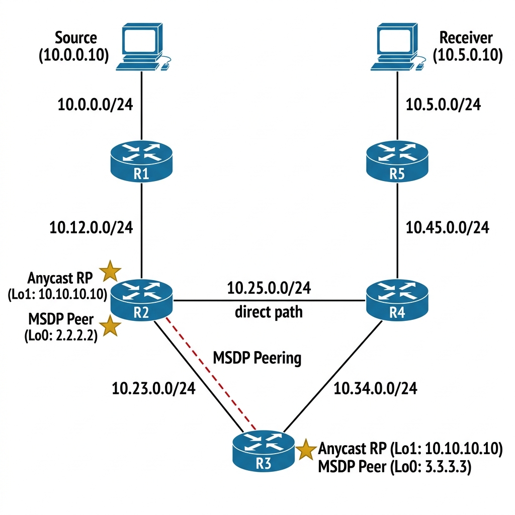
How Anycast RP Works
- R2 & R3 both have a Loopback with the same IP: 10.10.10.10
- Both advertise this Loopback via OSPF — routers pick the closest RP via IGP metric
- When a source registers with one RP (say R2), R2 sends an MSDP Source Active (SA) message to R3
- R3 now knows about the source & can build the SPT toward it
- If R2 goes down, OSPF reconverges & all routers shift to R3 — seamless failover
Configuration
R3 — Anycast RP + MSDP:
R3(config)# interface Loopback1
R3(config-if)# ip address 10.10.10.10 255.255.255.255
R3(config-if)# ip pim sparse-mode
!
R3(config)# router ospf 1
R3(config-router)# network 10.10.10.10 0.0.0.0 area 0
!
R3(config)# ip pim rp-address 10.10.10.10
!
!! MSDP peering with R2 using their unique Loopback0 addresses
R3(config)# ip msdp peer 2.2.2.2 connect-source Loopback0
R3(config)# ip msdp originator-id Loopback0
R2 — Anycast RP + MSDP:
R2(config)# interface Loopback1
R2(config-if)# ip address 10.10.10.10 255.255.255.255
R2(config-if)# ip pim sparse-mode
!
R2(config)# router ospf 1
R2(config-router)# network 10.10.10.10 0.0.0.0 area 0
!
R2(config)# ip pim rp-address 10.10.10.10
!
!! MSDP peering with R3
R2(config)# ip msdp peer 3.3.3.3 connect-source Loopback0
R2(config)# ip msdp originator-id Loopback0
All Other Routers (R1, R4, R5):
ip pim rp-address 10.10.10.10
Verification
R3# show ip msdp peer
Output:
MSDP Peer 2.2.2.2 (?), AS ?
  Connection status:
    State: Up, Resets: 0, Connection source: Loopback0 (3.3.3.3)
    Uptime(Downtime): 00:02:30, Messages sent/received: 5/5
    TLV messages sent/received: 5/5
  SA Filtering:
    Input (S,G) filter: none, route-map: none
    Output (S,G) filter: none, route-map: none
The Theory: Anycast RP with MSDP is the industry standard for large scale multicast redundancy. Unlike Auto-RP or BSR where a single RP is elected, here both R2 & R3 appear as the SAME RP (10.10.10.10). MSDP synchronizes the source registrations between them, so if R2 fails, R3 already knows about all active streams.
Now start the source using a continuous ping & check MSDP SA messages.
!! On Source — send multicast traffic
Source# ping 239.1.1.1 repeat 1000000 size 1000
R3# show ip msdp sa-cache
Output:
MSDP Source-Active Cache - 1 entries
(10.0.0.10, 239.1.1.1), RP 10.10.10.10, BGP/AS 0, 00:00:15/00:05:45,
  Peer: 2.2.2.2, Learned: 00:00:15, RPF peer: 2.2.2.2
R3 learned about source 10.0.0.10 via MSDP from R2. Now let us test failover.
Failover Test
!! On R2 — simulate failure
R2(config)# interface Loopback1
R2(config-if)# shutdown
Wait for OSPF to reconverge:
R5# show ip route 10.10.10.10
Output:
Routing entry for 10.10.10.10/32
  Known via "ospf 1", distance 110, metric 3, type intra area
  Last update from 10.45.0.4 on GigabitEthernet0/0, 00:00:10 ago
  Routing Descriptor Blocks:
  * 10.45.0.4, from 3.3.3.3, 00:00:10 ago, via GigabitEthernet0/0
R5 now points to R3 for the RP. Multicast continues to work. Bring R2 back:
R2(config)# interface Loopback1
R2(config-if)# no shutdown
Routers closest to R2 will switch back to R2 as the RP, & routers closest to R3 will stay with R3. Anycast RP provides both redundancy & load-sharing — this is why it is the production standard for multicast RP design.
Break It — Auto-RP Scope Too Low
Let me show you the single most common Auto-RP misconfiguration. Let us temporarily re-enable Auto-RP with a scope value that is too low.
!! Remove Anycast RP first
!! On all routers: no ip pim rp-address 10.10.10.10

!! Re-enable Auto-RP with scope = 1 (disastrously low)
R3(config)# ip pim send-rp-announce Loopback0 scope 1
R2(config)# ip pim send-rp-discovery Loopback0 scope 1
R5# show ip pim rp mapping
Output:
PIM Group-to-RP Mappings
(none)
Nothing. The scope (TTL) is set to 1, which means Auto-RP messages can only traverse one hop. R3’s RP-announce reaches R2 (one hop), but the Mapping Agent’s RP-discovery message from R2 cannot reach R5 (three hops away). R5 has no RP.
The fix:
R3(config)# ip pim send-rp-announce Loopback0 scope 16
R2(config)# ip pim send-rp-discovery Loopback0 scope 16
Always set the Auto-RP scope to be larger than the diameter of your multicast domain. I use 16 or 32 as a safe default.
RP Placement Design Principles
Based on real-world deployment experience, here is what I recommend:
- Place the RP near the center of the network — this minimizes the shared tree path length for all receivers
- Use Anycast RP with MSDP for production redundancy — it is the most resilient RP mechanism
- BSR is fine for multi-vendor environments — but make sure all routers support it
- Static RP is acceptable for small, stable networks or as a backup when dynamic mechanisms fail
- Never place the RP at the network edge — if the edge router goes down, the entire multicast domain loses its RP
- In IPTV deployments, the RP handles a lot of PIM Register traffic — size the RP router’s CPU for your expected source count
Key Takeaways
- Static RP is simple but has no redundancy or failover
- Auto-RP is Cisco-only, uses Dense Mode for the bootstrapping groups, & discovers RPs dynamically
- BSR is standards-based, uses PIM hop-by-hop flooding, & supports multi-vendor
- Anycast RP + MSDP is the production standard — same RP IP on multiple routers with source synchronization
- The scope/TTL value in Auto-RP must exceed your network diameter — too low & distant routers never learn the RP
- RP placement should be central — near the core, not at the edge