1. Introduction to Layer 4 Network Load Balancing
While Layer 7 load balancers analyze HTTP/HTTPS application payloads, high-performance network architectures—such as financial trading systems, gaming servers, database clusters, VoIP media gateways, and virtual firewall inspection hubs—require maximum packet throughput and ultra-low latency.
In Oracle Cloud Infrastructure (OCI), transport-layer distribution is handled by the Network Load Balancer (NLB).
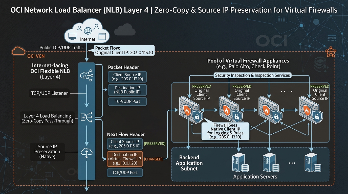
Operating at Layer 4 (Transport Layer) of the OSI model, the OCI Network Load Balancer performs non-proxied, zero-copy packet forwarding for TCP, UDP, and ICMP protocols.
2. Core Architectural Features of OCI Network Load Balancer
1. Zero-Copy Architecture & Sub-Millisecond Latency
The OCI Network Load Balancer does not terminate TCP connections or proxy application data. Packets are evaluated at the SmartNIC hardware layer and forwarded directly to backend servers, resulting in sub-millisecond latency overhead and near-line-rate packet processing.
2. Source and Destination IP Preservation
A key capability of the OCI NLB is IP Address Preservation:
* Source IP Preservation: The backend compute instance sees the original client IP address as the packet source IP, rather than seeing the IP address of the load balancer.
* Eliminates the need for complex proxy protocol headers (X-Forwarded-For) on backend databases, firewalls, and custom TCP/UDP services.
3. Symmetric Hash & Stateful vs. Stateless Forwarding
NLB load balancing decisions rely on n-tuple hash algorithms:
* 5-Tuple Hash (Default): Source IP, Source Port, Destination IP, Destination Port, IP Protocol. Ensures client traffic distributes evenly across backends.
* 3-Tuple Hash: Source IP, Destination IP, IP Protocol. Keeps all connections from a specific client IP pinned to the same backend node.
* Symmetric Hashing (Firewall Mode): Guarantees that bidirectional flows between Client and Server route through the exact same virtual firewall instance in both request and response directions, preventing asymmetric routing connection drops.
3. NLB vs. L7 Load Balancer Technical Comparison
| Feature | Network Load Balancer (NLB – Layer 4) | Flexible Load Balancer (L7) |
|---|---|---|
| OSI Layer | Layer 4 (TCP, UDP, ICMP). | Layer 7 (HTTP, HTTPS, HTTP/2). |
| Packet Handling | Direct packet pass-through (Non-proxied). | Reverse proxy (Decouples client/backend TCP). |
| SSL/TLS Termination | Not supported (Passes encrypted TLS to backends). | Supported (SSL Offloading & Re-encryption). |
| Latency Profile | Ultra-Low (< 1 ms). | Low (~ 2-5 ms due to L7 parsing). |
| Source IP Preservation | Native (Backends see raw client IP). | Requires X-Forwarded-For HTTP header. |
| Virtual Appliance Insertion | Ideal for Virtual Firewalls (Palo Alto, Fortinet). | Not suitable for inline L4 virtual firewalls. |
| Cost | Free (Zero hourly service fee; data rates apply). | Fixed hourly fee + Capacity usage. |
4. OCI Web Console (GUI) Step-by-Step Walkthrough
Follow these operational steps to provision a Network Load Balancer fronting a pool of Palo Alto Virtual Firewalls.
Step 1: Navigating to Network Load Balancers in the Console
- Open Navigation Menu (
≡) ➔ Networking ➔ Network Load Balancers. - Select your compartment (
Network-Compartment). - Click Create Network Load Balancer.
Console Path: [≡ Main Menu] ➔ [Networking] ➔ [Network Load Balancers]
Step 2: Configuring Basic NLB Parameters
- In the creation modal:
- Name:
NLB-Firewall-Ingress - Visibility: Select Private (or Public if fronting external traffic).
- VCN:
VCN-Hub-Security - Subnet:
Subnet-DMZ-Regional - Click Next.
Step 3: Configuring Listener & Backend Set for Firewall Redundancy
- Listener Configuration:
- Listener Name:
Listener-All-TCP-UDP - Protocol: Select Any (or TCP / UDP).
- Port: Select All Ports (Port
0). - Backend Set Configuration:
- Backend Set Name:
BES-Firewall-Pool - Preserve Source IP: Check Enable Preserve Source IP.
- Algorithm: Select 5-Tuple Hash (or 3-Tuple Hash).
- Health Check Protocol: Select TCP | Port:
8080(Firewall keepalive port). - Add Backends: Select
FW-Instance-01(10.0.1.10) andFW-Instance-02(10.0.1.11). - Click Create Network Load Balancer.
5. Common Architectural Misconceptions & Pitfalls
Misconception 1: “Network Load Balancers Support Host-Based HTTP URL Routing”
- Reality: NLBs operate at Layer 4 and cannot inspect HTTP headers, URL paths, or cookies. URL path-based routing (
/api/*vs/web/*) requires a Layer 7 Flexible Load Balancer.
Misconception 2: “Source IP Preservation Works When Backend Instances Are in the Same Subnet as NLB”
- Reality: If an NLB forwards traffic to a backend instance residing inside the exact same subnet, Source IP Preservation can cause asymmetric return routing (backend replies directly to client IP instead of routing back via NLB). Best practice: Place NLBs and backend instances in distinct subnets.
6. OCI NLB vs. Other Cloud Platforms
| Feature | Oracle Cloud Infrastructure (OCI) | Amazon Web Services (AWS) | Google Cloud Platform (GCP) |
|---|---|---|---|
| Layer 4 Load Balancer | Network Load Balancer (NLB) | Network Load Balancer (NLB) / Gateway LB | Passthrough Network Load Balancer |
| Protocols Supported | TCP, UDP, ICMP | TCP, UDP, TLS | TCP, UDP, ICMP, ESP |
| Source IP Preservation | Native (Toggle per backend set) | Native | Native |
| Firewall Insertion Support | Built-in via NLB & Symmetric Hash | Requires AWS Gateway Load Balancer (GWLB) | Supported via Internal Passthrough NLB |
| Managed Service Base Cost | FREE | Hourly fee + NLU usage | Hourly fee + Processing fee |